This thread has been locked.

If you have a related question, please click the "Ask a related question" button in the top right corner. The newly created question will be automatically linked to this question.

TPS61071: Differs in load transient response with the same load

Part Number: TPS61071
Other Parts Discussed in Thread: TPS61073, TPS61070

Hi TI

I hope that you can help me understand a phenomenon, that I have not seen before.

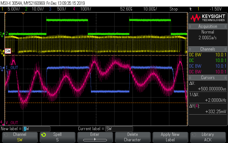
It seams that the load response/transient of the TPS61071 differs randomly to the same switching load

setup:
V_in=3V
V_out=5V

load:
80mA
f=1Hz
D=50%

In the image below: Ch1=V_in, Ch3=I_out and Ch4=V_out

Adding output capacity solves the problem, but I would very much like to know the cause of this behavior??

I would appreciate any information you can provide on this subject.

  • Dear User:

    It's normal behavior.

    For TPS61071, the converter will forecast a duty cycle base the Vin, Vout and other factors at first. Then modified according to the error amplify in control loop with small range. The control loop only handle small signal error. If the Vfb has big difference than target, the converter will change the forecast duty cycle and modify again to make sure it remain in the range. 

    So in some case, for one target Vout, the converter may have different forecast value and keep it in the range.

  • Hi Minqiu

    But shouldn't the forecast be the same, when all of the parameters is the same?

    In my own investigations (pictures below) it seams that the converter tries to decrease the duty cycle, but when its not possible to decrease the duty cycle any more it stops switching?

    What is the cause of this? it is not every load cycle, but only some? and it should be a fixed frequency converter

  • Dear User:

    The forecast value will make it locate around the target value. For example, 5.01V and 4.99V are all within the range of the target 5V. 

    For the latter issue, I suspect it may enter into PFM with too high Vout. The loop seems not stable at this time. May you share the schematic with us? Besides, the frequency of the load transient is what you need, or just for test?

  • Dear User:

    As long time not hear you, I assume you have solved the issue. I'll close this post.

    If not, just reply below. Thank you~

  • Hi Minqiu

    Thank you for the reply.

    So even though it is a fixed frequency converter. it is still able to modulate its frequency in some cases ? Or is it a result of the converter is switching off when V_out is too high?

    The load is just for testing this behavior of the converter, the load would be 5mA to ~90mA switching with 22kHz

    I have attached the schematic below.

    .

    The device is battery supplied and contain more input capacity at other locations. How ever increasing the input capacity to 2x4.7µF along with 3x4.7µF on the output solved the issue. 

  • Dear User:

    The converter need some time to recover to stable. So if the load transient is too fast, there is a risk for unstable.

    May I get your double confirm that you are using the TPS61071? If so, I need to check in our lab to see if it will stop switching if Vout is higher than target.is converter is fixed frequency, but it will skip some pulse if the Vout is much higher than the target. Details could be seen in  

    Besides, C2, R3 is not a normal usage for TPS6107x. I'm not sure if it will impact the stability. 

  • Hi Minqiu

    Thank you for the reply

    Do you know how fast transients the converter can handle? (rise time/ frequency?)

    Yes it is the TPS61071 fixed frequency converter, it would be great information, thank you.

    The datasheet recommends additional capacitance(C2) in parallel with R1, when R2 is significantly lower than 200KOhm (R1 at 1Mohm is not desired). R3 is to ensure some resistance at high frequencies(probably not necessary).

  • Dear User:

    Sorry that I'm out of office today. I may give you reply in Friday. Thanks for your kind patience.

  • Dear User:

    Sorry for keep you waiting. 

    The maximum frequency of the load transient for converter support is mainly determined by the control loop and Vin, Vout condition. Mainly less than 500 Hz. 

    And R3 is not necessary.

  • Hi Minqui

    Thanks for you response

    Okay so the converter do not has time to recover. Do you know what the optimal conditions for the converter should be for this concern?

    Any information about if it stop switching due to over voltage?

  • Dear user:

    I have re-produced the behavior. And I`m trying to involve team to find the root cause.

    Thanks for your patience.

  • Dear User:

    I have checked with team. The root cause is that the loop is so unstable and the converter set the duty cycle as 0%. We also reproduced such phenomenon during the load transient when Vin is close to Vout. And it will recover to continues switching soon when Vout is back. It's normal behavior. 

  • Hi Minqiu 

    Thanks for the support and information!

    How can I improved the loop stability? or is it impossible with load transients faster than 500Hz?

    Best regards
    Anders

  • Hi Anders:

    Remove the R3, and change the value of C2 could improve the loop performance. 

    I think it's possible to achieve 500hz, but I'm so sorry that I can't do the test for you as I'm out of office in these two weeks.

  • Hi Minqiu

    Thank you for your previous support.

    In the process of understanding the behavior of the TPS61071, I tried the TPS61073 from the same family.

    With the same load and the exactly the same setup, the TPS61073 transient response is very difference from the TPS61071. 

    The TPS61071 is as previous discussed unstable with ~500mVpp ripple.

    the TPS61073 seams very stable with a ~200mVpp ripple.

    • The transient response looks much faster than the TPS61071, is this the case? I would have expected it to be vise versa, since the TPS61073 goes from power safe mode(beat skipping) to normal mode
    • The datasheet states that in PWM mode there is no difference, but how about the when it is a pulsed load?

    The load is a 160mA 50% duty cycle with a frequency of 22kHz

    Best regards
    Anders

  • Hi Anders:

    So sorry that I can't back lab these days as a virus outbreak here. It may still have one more week.

    Yes, the mainly difference of the TPS61071 and TPS61073 is the current limit.(And the enable logic)

    TPS61073 has the PFM, which used the threshold control principle. It could help to reduce the overshoot if it exceed the threshold with short delay.  And the Vout will remains little larger than normal operation.

    But for TPS61071, if the loop is modified well and no such quick load transient, the vout ripple will be much smaller. (Such as Fig 18 in datasheet, Vin=3.6, Vout=5V. Io=20mA-80mA, the Vout ripple is less than 50mv)

  • Hi Minqiu 

    Thank you for your support even with the virus outbreak!

    My current load is 160mApp with a frequency of 22kHz, which is way above the maximum 500Hz for the TPS61071.

    I am considering the TPS61070 instead and accept its ripple in power save mode. 

    Best regards
    Anders

  • Hi  Anders:

    Sincere thanks for your kind understanding. And it's my pleasure to deep dive the issue with you. 

    If you would accept the ripple caused by the PFM, the TPS61070 or TPS61073 is the better choice. The response will be much quick once it exceed the threshold.

  • Hi Minqiu

    I will try out the TPS61070

    Again thank you for your support