This thread has been locked.

If you have a related question, please click the "Ask a related question" button in the top right corner. The newly created question will be automatically linked to this question.

BQ4050: battery capacity jump

Part Number: BQ4050
Other Parts Discussed in Thread: GPCCEDV, BQ78350-R1, BQ78350

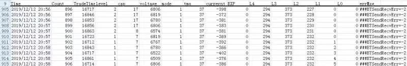
Hi, my customer is using BQ4050 for 2 series battery pack gauging, the capacity jumps from 17% to 7%.

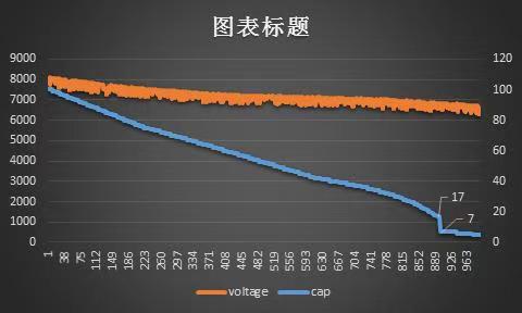
The load doesn't increase or decrease apparently, shown below:

what may cause such jump?

what information we need to provide to find the cause of this jump?

  • Hi Howard,

    Have you configured the CEDV parameters for the gauge? This is necessary for gauging accuracy. When the SOC drops to 7% it means that the EDV2 voltage has been reached. Please see the online GPCCEDV tool for more information on this process: http://www.ti.com/tool/GPCCEDV

    Here is the recommended flow for using fixed EDV or compensated EDV (better). This is from the app note 'Using the BQ78350-R1' gas gauging section. (BQ78350-R1 is also a CEDV gauge so the instructions are similar).

    Setting Design Capacity

    The default maximum chemical capacity of the battery is 4400 mAh. Design Capacity should be set based on the battery pack specification. Design Capacity is set in both mAh and cWh. The [CapM] setting in BatteryMode() determines which units are used to report data for capacity parameters. It is recommended to initialize Learned Full Charge Capacity to the same value as Design Capacity mAh. This will improve the accuracy after a reset until a learning cycle has completed to update the Full Charge Capacity.

    Setting the CEDV Gauging Parameters

    Setting the [EDV_CMP] bit to '1' in CEDV Gauging Configuration puts the gauge in CEDV mode. This selection will compensate both temperature and load. The Compensated End-of-Discharge (CEDV) gas gauging algorithm requires seven coefficients to enable accurate gas gauging. The default values are generic for Li-CoO2 chemistry, but these coefficients should be recalculated and updated based on the battery. The CEDV coefficients ensure gauge accuracy over temperature and current load. The procedure to gather the required data and generate the coefficients can be found at http://www.ti.com/tool/GPCCEDV.

    The GPC tool requires six data log files of a continuous discharge (3 different temperatures and 2 different discharge rates). The logs should contain columns for time (in seconds elapsed), voltage (in mV), current (in mA where discharge current is negative), and cell temperature (in degrees C). Data files should be stored in csv format.

    There are seven CEDV parameters in the report that should be programmed into the bq78350 Data Memory:

    • EMF (EMF)

    • EDVC0 (C0)

    • EDVC1 (C1)

    • EDVR1 (R1)

    • EDVR0 (R0)

    • EDVT0 (T0)

    • EDVTC (TC)

    A simpler but less accurate way to set up the gas gauging feature is to use EDV gauging. Setting the [EDV_CMP] bit to '0' in CEDV Gauging Configuration puts the gauge in EDV mode.

    EDV mode uses fixed values for EDV1 and EDV2 that will not be compensated for temperature or current load. These values can be selected by one of the below approaches:

    Rough Estimation

    – i. Find the discharge curves for the cell from the manufacturer

    – ii. Pick the capacity at the rate you intend to discharge and the voltage where you intend to stop. This is the design capacity and the EDV0.

    – iii. Calculate 97% of the capacity and find the voltage on the curve. This is EDV1

    – iv. Calculate 93% of the capacity and find the voltage on the curve. This is EDV2

    Better Calculation

    – i. Set the battery in the normal operating conditions and let the temperature stabilize.

    – Charge the pack to full. Make sure overcharge protections and voltage protections are set to allow full range while learning the battery.

    – iii. Log discharge until you reach the “empty” voltage. If using average cell voltage gauging allow some margin for the CUV threshold in setup so you can reach empty.

    – iv. Calculate discharged capacity by adding the current x incremented time at each log point.

    – v. Select EDV0 voltage where the pack is “empty”, either the manufacturer stated cutoff voltage or some selected value with margin

    – vi. Calculate 97% of the passed charge to the EDV0 point, find the corresponding voltage in the log. This is EDV1.

    – vii. Calculate 93% of the passed charge to the EDV0 point, find the corresponding voltage in the log. This is EDV2.

    After EDV1 and EDV2 values are determined, load the values to Data Memory and run confirmation cycles as needed to verify performance.

    Best regards,

    Matt

  • Matt,

    we have configured the CEDV parameters for the gauge.

    I have several questions:

    1. If we use CEDV instead of EDV, let's say we have already programmed the gauge with the seven CEDV parameters.

    The EDV0, EDV1 and EDV2 are calculated by the gauge during the one discharge process, it's not a fixed value, right?

    For example, the end equipment is a ePOS. We discharge the battery at 1C from 100% SOC to 50% SOC, the EDV2 which corresponds to 7% SOC may be calculated to be N1 voltage, then if we start to discharge the battery at 0.5C from 50%, the EDV2 calculated may be N2 voltage, right? The exact voltage corresponding to 7% SOC, 3% SOC and 0% SOC is always changing during one discharge cycle, right?

    2. I see that the capacity jumps from 17% to 8% along with the voltage jumps from 6.806 to 6.574V in the picture I posted in the thread. Is it true that CEDV gauge is not suitable for application where the battery voltage will jump? Since CEDV gauge will use battery voltage to estimate SOC, if battery voltage jumps, SOC will jump, right? Will impedance tracking device behave better in such cases?

    3. Is it true that if we can keep the battery voltage decrease smoothly, the reported SOC will be smoothly decreasing instead of suddenly jump?

  • Hi Howard,

    Matt is on vacation this week, so his response will be delayed.  I have not worked with this device in detail, but I can try to offer a few comments based on my understanding.

    While in CEDV mode, the EDV0/1/2 levels are generally recalculated regularly during operation, I believe this is every 1-sec.  If you have a log file of a discharge and note the EDV levels reported, you should see them changing as the load and temperature change.

    However, the EDV voltage recalculations can be overridden, with them forced to stay fixed, depending on settings within the device.  The [FIXED_EDV0] bit forces the EDV0 voltage to not be modified, and the [EDV_CMP] bit can disable all dynamic calculations for the EDV voltages, even if in CEDV mode.

    The jump that occurs at 7% is correcting errors that have accumulated earlier in the discharge.  While it appears the capacity slowly reduced to 17% before the jump, actually the capacity had really been slowly reducing to ~7%.  The device corrects the error when it reaches EDV2.  Have you completed a learning cycle on the battery?  If not, then it is not unexpected to have a jump, since your Full Charge Capacity is probably incorrect, it needs the learning cycle to learn the capacity of this specific pack.

    You can also use the CEDV Smoothing feature, which rather than the SOC dropping immediately to 7%, it smoothly ramps the SOC downward as it nears this voltage.

    CEDV gauging can be used in systems which incur voltage jumps, you may just need to tune the smoothing feature for your specific case.  Per your question #3, even if the voltage was decreasing very slowly and smoothly, if the gauge reaches EDV2 and the reported SOC is above the 7%, it will still need to correct the error, either through a jump or a smoothed transition.

    Thanks,

    Terry

  • Terry,

    thank you very much.

    Now we have almost find the cause of the jump.

    When the POS is in sleep mode. The POS itself will consume 100uA, and BQ4050 will consume about 200uA measured. (BQ4050 in SLEEP mode, CHG off, DSG on, no SBS communication). The total current consumption is about 300uA.

    The battery design capacity is 2300mAh. 

    They have put the POS in sleep mode for more than 10 days so it causes the capacity jump. And the discharge current is so small that's beyond the Coulomb counter's resolution. The actual capacity has decreased a lot (for instance from 70% to 60%), but the gauge still think it's 70%. And this error is corrected at 7% point.

    My questions would be:

    1. what's the minimum current that can be detected and accumulated by the Coulomb counter? Are there any way we could detect the discharge current at sleep mode?

    2. Are there any way we could decrease the current of BQ4050 when it's in SLEEP mode, CHG off, DSG on, no SBS communication? In datasheet, the typical value of Isleep is 75uA. But the measured value is 200uA. Is this value related to the peripheral circuit of BQ4050?

    The Isleep is a very important parameter. The customer will have finished goods inventory which will have battery charged to about 60% capacity (2300mAh*0.6=1380mAh). 1380mAh/(200uA+100uA)=4600h=191 days. Which means the battery will be over discharged at 191days, but they can only accept it to be discharged after 365 days.

  • Hi Howard,

    The coulomb counter in the bq4050 can detect currents even below the reported LSB of the measured current, which I recall is around 3.5uV, although I don't have a firm value for the minimum.  Note the device also estimates self-discharge of the cells and includes this in the coulomb count, see the Self Discharge Rate parameter.

    Regarding the power in SLEEP mode, you can extend the Sleep:Voltage Time and Sleep:Current Time parameters longer, so the device wakes less often to do measurements.  You may also consider whether you can instead use SHUTDOWN mode, which will have much lower current.

    Thanks,

    Terry