This thread has been locked.

If you have a related question, please click the "Ask a related question" button in the top right corner. The newly created question will be automatically linked to this question.

TPS63020 not regulating efficiently at Vout = 5V

Other Parts Discussed in Thread: TPS63020

Hi,

I'm trying to design a number of TPS63020 circuits and snyc them together. My input voltage range is 3.5 - 5.5 V and my desired outputs are as follows:

3V @ 400mA

4V @ 800mA

5V @ 900mA

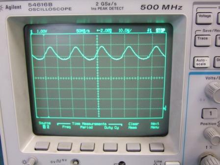
I can get the 3V and 4V versions working fine but am having trouble with the 5V one. It draws up to 25% more current at 5.5V (in) than it does at 5.0V (in). It also won't regulate when the input is below 4.0V. Are these chip limitations or am I doing something wrong?

regards

Garth

  • Can you post a schematic of your circuit?  Is this testing being done on the EVM or on your own board?  Can you post waveforms of what happens when the output doesn't regulate at 4V in?  What is your load during this testing?  Does the circuit behave the same with no load and full load?

    The TPS63020 can do a 4V to 5V conversion.  Most likely, the cause is a non-optimal layout or incorrect component selection.

  • Attached is a schematic and layout of the circuit which I tried to keep the same as the datasheet. However when it wasn't working I added some more capacitance (2 x 10uF) at the input and output. I have posted a plot of the output when the input is at 5.5 V and the circuit is drawing more current than it should (I tried zooming in the timescale to catch the actual switching frequency but it was too fast for my CRO). I tested the circuit with both a 10 Ohm and a 5 Ohm load and it was doing the same for both. Under "no load" condition the output was fine.

    Chris Glaser said:

    Most likely, the cause is a non-optimal layout or incorrect component selection.

    I'm using one of those Coilcraft XFL4020 inductors and have tried using 1.5uH as well as 2.2uH.

    6355.TPS63020 PSU.pdf

    6835.TPS63020 Layout.pdf


  • Thank you for posting your schematic and layout.  Yes, the XFL4020 will work fine.  A few suggestions:

    Your ceramic input and output caps will lose most of their capacitance due to the DC bias effect.  This is an effect on ceramics--when a ceramic holds a DC bias across its terminals, the effective (real) capacitance decreases.  With 5V or 5.5V on these 6V caps, the real capacitance could be reduced by as much as 80%.  I would get 10V or 16V caps and try again with the same 10uF value.  Also, I assume these are X5R or X7R dielectrics?  Do not use Y5V or Z5U as their capacitance varies too much and they have much worse DC bias characteristics.

    I would try the above first.  With the reduced capacitance, you may be violating equation 6 in the datasheet which gives a minimum value for the capacitance.

    If the above doesn't help, I would then try to lower the impedance of your feedback divider.  With a 2 Meg high side resistance, it will be very susceptible to noise.  I would try lowering the resistors by an order of magnitude--to 200k and 22k--and see if that makes a difference.

    Assuming you have a ground plane on layer 2 that is uninterrupted below the IC, the layout looks fine.  Thank you for copying the EVM's.

  • Thanks Chris,

    I beefed up the voltage on the input and output capacitors to 16V (1206 capacitors) and that seemed to help a lot. The chip was regulating all the way from 3.5 - 5.5. But I found that my current was still varying a lot especially at high voltages. So I reduced the impedance of the feedback divider as you suggested but still no luck. I tracked this issue down to some variable contact in the banana plugs I was using to connect to the power supply. Once I replaced these plugs with a more robust connection it worked fine.

    thanks for your help.

  • Excellent!  Thank you for replying with the solution.

    I would also recommend that you increase the voltage rating on the input caps for the 3V and 4V supplies just in case.