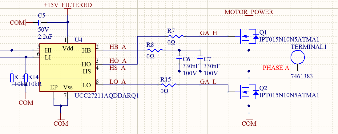
I'm using a UCC27211 to drive a half bridge in a 3-phase motor controller. I ran into issues in a previous version of my design where the UCC27211 would get hot. I respun the board because I was seeing ringing on the HO pin, mainly due to the driver being somewhere around 3 inches from the FET. The new board places the driver ~400 mils from the gate of the FET.
At first test, we believe we had some shoot-through, and began testing to verify. We disconnected the higher voltage from the board and powered logic only.
At first power-up, everything appeared to be fine. We tested drive voltages, looked at input signals. What we found was that after about 10 min of testing, the 15V power rail was reading about 5V, and the UCC27211 drivers were hot. Again, our Motor Power voltage was 0, only the logic power supplies were on. So the FETs only saw GND and VG, if anything. I should note that the 15V supply is rated to supply up to 1 amp.
Bootstrap capacitance was calculated based on Qcg of the FET, and later fine tuned when it was realized that Vgs for Q1 was insufficient as calculated to push the FET out of the linear region and into saturation. Operating frequency is 32kHz.
Can someone shed some light?