This thread has been locked.

If you have a related question, please click the "Ask a related question" button in the top right corner. The newly created question will be automatically linked to this question.

BQ76920: How much max Ah does BQ76920 supports?

Part Number: BQ76920
Other Parts Discussed in Thread: BQ78350, BQ40Z50, BQ4050, BQ34110, BQ34Z100-G1, BQ34Z100, BQ34Z100EVM

Hi,

We are designing the coulomb counter and battery monitor for 12V (4-cell LiPo) battery with 30Ah capacity. Please note that we are not including any charging circuit and the charging would be done externally. I would like to know if BQ76920 supports our required capacity? Also, the parameters that we need to take care of.

In addition, is there any other alternative for similar specs that we can consider (excluding BGA packages)?

Thanks,

Muhammad Awais

  • Hi Muhammad,

    This device measures and reports the current flowing through the sense resistor.  You just need to choose a sense resistor such that the maximum current does not exceed the measurement range (200mV).  The device is not integrating the current values, you can do that in your host processor or by using the bq78350 companion gauge.

    You might consider the BQ40z50 or BQ4050, both are in 32-pin QFN and include monitoring, protection, cell balancing, and gauging.  Since these devices do integrate the charge over time, you need to make sure the maximum does not exceed their accumulated charge range.  If so, this can be worked around using current scaling or capacity scaling, which effectively tricks the device into thinking the current is smaller than it is, so the charge values accumulated are reduced.

    Thanks,

    Terry

  • Hi Terry,

    Thanks for your kind reply. We will look into further. 

    Also, can you please confirm that bq34110 can be used for applications where we are regularly consuming the battery? Actually we are more comfortable with TSSOP. 

    Thanks,

    Muhammad Awais

  • Can you please also confirm if bq34410 supports LiPo?

    Kind regards,

    Muhammad Awais

  • An additional questions and would be great if you can answer this as well.

    Can you please confirm if the li-Ion charge controller and gauge IC could be used for li-Po? Seems like they have similar chemistry.

    Thanks,

    Muhammad Awais

  • Hi Muhammad,

    The bq34110 can be used with LiFePO4 cells, as well as the bq4050, the bq40z50, and the bq34z100-G1.  

    The bq34110 and bq34z100-G1 are similar in that they only integrate gauging, not protection or cell balancing.  They perform gauging by measuring the top-of-stack voltage and modeling the entire pack as a single cell.  The bq34110 uses CEDV gauging algorithm, which is based primarily on coulomb counting.  For it to track the battery aging properly, your pack needs to cycle between full charge and the EDV2 7% SOC level somewhat regularly, it is only when it traverses those endpoints that it determines how much the capacity has decreased due to aging.

    The bq34z100-G1 uses Impedance Track algorithm, which is much more advanced and can be more accurate, but it is also more complex to setup and tune.  This gauge does not require the pack to cycle between full and 7%, it can determine aging if the pack enters a relaxed state (there are many conditions that must be met, though).

    Both the bq34110 and bq34z100-G1 are in TSSOP.  The bq4050 (32-QFN) uses CEDV, while the bq40z50 (32-QFN) uses Impedance Track, these also integrate protection with high-side NFET drivers as well as passive cell balancing.  They measure the voltage of each series cell and gauge and protect based on the measurements of each cell.

    Another option is the bq78350-R2 + bq76920.  This two-chip combination implements CEDV gauging on each cell individually, as well as protections (with low-side NFET protection FET drivers) and cell balancing.  Both devices are in TSSOP.

    When you use Impedance Track gauging with LiFePO4 chemistry cells, you need to configure the device properly, since these cells require a longer relax time before the gauging accepts their voltage as completely settled and uses it for the gauging.

    Thanks,

    Terry

  • I discussed the gauge options in the previous post.  I am not really familiar with our charger solutions for LiFePO4, I recommend you post that question under the battery charger e2e forum, someone from that group can respond better than I can.

    Thanks,

    Terry

  • Hi Terry,

    Thanks for your kind reply and details. Few comments and questions;

    => You are talking about LiFePO4, while we are using LiPo. Can you please confirm that bq34z100-G1 and bq34110 supports LiPo? 

    => Can you please confirm if bq34110 only applies for batteries that rarely discharge? In our case we will be continuously using the battery. 

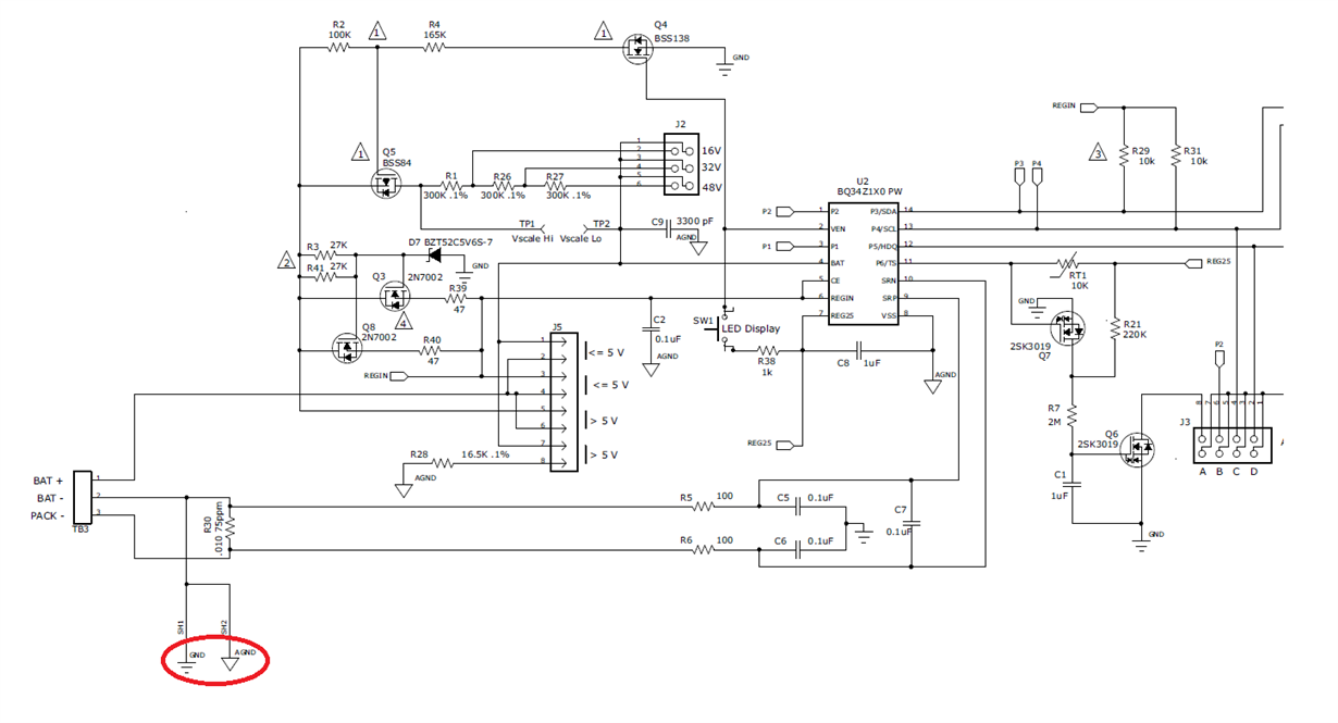
    => We thought to proceed with bq34z100-G1. As per the reference design we have BAT+, BAT- and PACK-. I know that BAT+ and BAT- will be coming from battery plus and minus and PACK- is where we will have our system ground but in this case how the digital pins like I2C and device ground? As per reference design they all are refernced with respect to the BAT-. Please clarify this as so that I can correctly connect this to my system ground. Please note that bq34z100 will added on our board. 

    => C5 and C6 from above snpashot is referred to which ground? From symbol it seems like it is GND but there is no name next to it. 

    Kind regards,

    Muhammad Awais

  • Hi Muhammad,

    Ah, sorry, yes I was talking about LiFePO4.  These devices all support Li-polymer.

    The bq34110 can be applied to devices that are regularly cycled or rarely discharged, it does not require a rarely discharged application.  The end-of-service determination feature within that device (which is intended for rarely discharged applications) is a separate module from the gauging.  So you can just use the gauging and leave the end-of-service feature deactivated.

    Note that bq34z100 and bq34z100-G1 are different devices.  You should focus on the bq34z100-G1, it is more recently updated.

    Regarding the grounds in the schematic, the AGND is used for sensitive analog measurements, so it should be routed to avoid DC currents flowing across it, the DC current will flow from BAT- to the sense resistor, then to PACK-, but AGND will be Kelvin-connected back to the BAT- point.  The GND connection is used for less sensitive purposes, such as the LED currents.  Note that the pack voltage measurement is measuring the differential voltage between the BAT pin and the VSS pin (which is connected to AGND).  So any noise on AGND can also impact the pack voltage measurement.

    Regarding C5 and C6, it is actually better to instead just use C7 and remove C5 and C6.  C7 provides differential filtering of differential signals across the sense resistor, while C5 and C6 could couple in noise from the GND line to the coulomb counter.

    The difference between PACK- and BAT- will only be the voltage across the sense resistor.  Since your system ground (PACK-) is the ground for your processor which is talking to the bq34z100-G1, your digital bus will be referred to that level with respect to the processor.  From the bq34z100-G1 standpoint, its ground is BAT-, so will have the extra voltage drop across the sense resistor included, but this should be kept low enough voltage to not impact the bus communications.

    Thanks,

    Terry

  • Hi Terry,

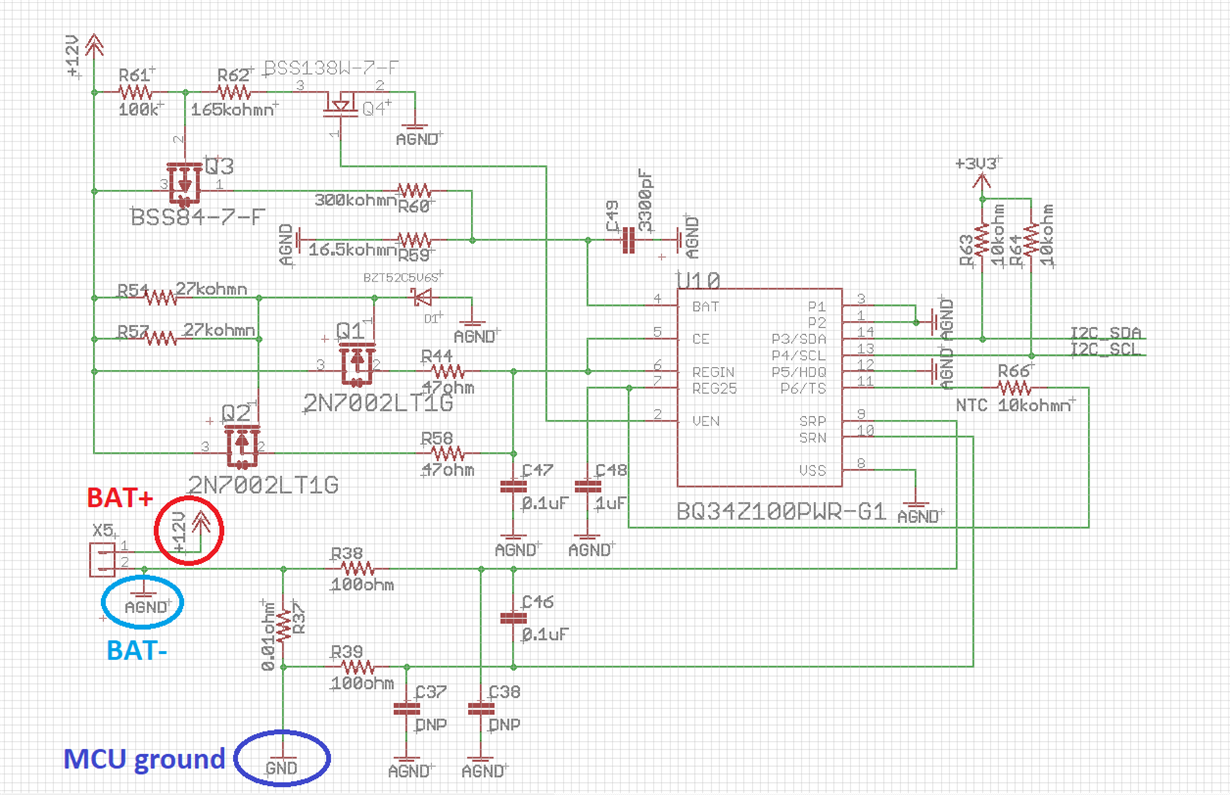
    Yeah, I am using bq34z100PWR-G1. I have just finished the schematic and need your help to review it. Please have a look on the snapshot given below, after that there are few questions related to it;

    => Please note that I have +12V the battery positive and AGND as battery negative, same AGND is going and connecting to VSS of BQ34Z100. GND (marked in blue) will be connected as a GND to rest of the system (MCU and all other circuitry except VQ34Z100PWR). Please confirm if this all is fine?

    => Reference design have jumpers and potential divider network for either 16V, 32V and 48V. In our case the VBAT max will be 12V. Can you please suggest that what should be the VBAT pin voltage that we should have via this potential divider? For now I have kept it with respect to VBAT of 16V.  

    => Can we run the REGIN pin from 3.3V that is locally generated? If yes then how much the current consumption will be. I have checked the datasheet but unable to find any relevant figures. Secondly, do we need to keep BQ34Z100 to AGND (BAT-) in case of local 3.3V? I am thinking if we may avoid additional circuit (Q1, Q2, R44, R58, R54, R57 and D1) in that case. But in general I am fine to keep it like this and in any case the pull-ups on I2C will be connected to MCU 3.3V.

    => We need to monitor the temperature, for now I have just added R66 at pin 11 but can we add a thermister near the batteries and then connect it to the REG25 pin and TS (pin 11) via header. I am just afraid if this will add any noise via wires.

    => Please let me know if there is any other issue with this circuit. 

    Thanks,

    Muhammad Awais

  • Hi Muhammad,

    I believe your connecting VSS to AGND=BAT- is correct.  You show a sense resistor of 10mOhm, how much is the max current you expect to flow through that?  If it could be more than tens of amps, it could cause you issues during communication, since the gnd for your MCU would then be hundreds of mV different vs the gnd for the gauge.  If you have issues there, you may need to reduce the sense resistor value.

    I don't understand why you have two sets of circuits to supply REGIN (R54/R57, Q1/Q2, R44/R58)?  I believe you only need one, so can remove R57, Q2.  I'm also not sure why you have the R44 and R58 resistors, I believe those can be removed/shorted out.  Q1 is effectively a source follower, with its source driving REGIN.  Given your voltage is not too high, you may also be fine to remove R54 and connect the drain of Q1 directly to BAT+.  R54 helps move some of the thermals away from the FET, to avoid it getting too hot.

    The REGIN current can add 5-10mA during flash writes, that is the dominant current load.  The remaining items are <1mA.

    The gauge needs to keep VSS connected to BAT-, otherwise the cell voltage measurement will have significant error.  However, you can generate the REGIN voltage differently than using this circuit if you prefer.

    The voltage at BAT in multicell mode needs to stay below 900mV max.  See the datasheet section 7.3.8 Voltage Measurement and Calibration.

    Thermistors are normally attached to cells, so they will generally have somewhat long wires connecting them to the PCB.  Just try to keep them as short as possible and keep them close together, maybe as a twisted pair if practical.

    I will also defer to my colleagues who have more expertise on this device, in case they have better suggestions.

    Thanks,

    Terry

  • Hi Terry,

    I believe your connecting VSS to AGND=BAT- is correct.  You show a sense resistor of 10mOhm, how much is the max current you expect to flow through that?  If it could be more than tens of amps, it could cause you issues during communication, since the gnd for your MCU would then be hundreds of mV different vs the gnd for the gauge.  If you have issues there, you may need to reduce the sense resistor value.

    Thanks, I will take care of the resistor value. 

    I don't understand why you have two sets of circuits to supply REGIN (R54/R57, Q1/Q2, R44/R58)?  I believe you only need one, so can remove R57, Q2.  I'm also not sure why you have the R44 and R58 resistors, I believe those can be removed/shorted out.  Q1 is effectively a source follower, with its source driving REGIN.  Given your voltage is not too high, you may also be fine to remove R54 and connect the drain of Q1 directly to BAT+.  R54 helps move some of the thermals away from the FET, to avoid it getting too hot.

    I have followed the reference document bq34z100EVM from TI that has these additional MOFETs and resistors. May be the purpose is to reduce the Rds (add another in parallel). 

    The voltage at BAT in multicell mode needs to stay below 900mV max.  See the datasheet section 7.3.8 Voltage Measurement and Calibration.

    Thanks, setting the resistors with respect to this voltage. By the way can we use this BAT pin to monitor the battery input voltage and transfer this information to MCU via I2C?

    I will also defer to my colleagues who have more expertise on this device, in case they have better suggestions.

    Sure, please forward it to them, just in case they will have any comment on it. 

    Thanks for the help.

    Kind regards,

    Muhammad Awais

  • Hi Muhammad,

    I don't see why the parallel FET and resistors are included.  I have passed your thread onto my colleagues, although they may not respond until next week, due to vacations.

    Regarding monitoring the voltage, the gauge will report the stack voltage it measures, your MCU can read this using the Voltage() command over I2C.  There are many items you can read from the gauge using commands, including voltage, current, temperature, SOC, etc.

    Thanks,

    Terry

  • Thanks Terry for the overall help. I will look forward to the reply from your colleagues. 

    Kind regards,

    Muhammad Awais

  • Hello Muhammad,

    The bq34z100-G1 uses the voltage divider and scales it back via FW on the BAT pin. You will want to use this battery stack voltage for gauging. You can also read it via I2C.

  • Hello Kang and Terry,

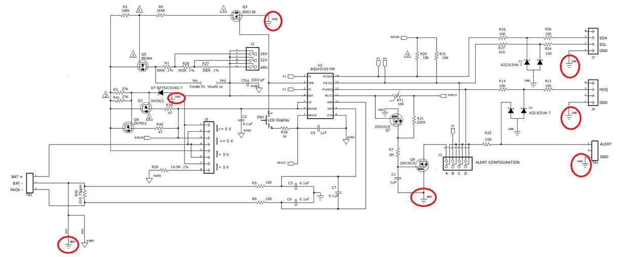
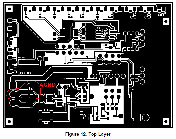
    I have a confusion! Currently, I am on the layout phase and I have reviewed the reference design schematics plus layout diagrams that are given in the bq34z100EVM documentation. I can see that BAT- has the AGND and GND (circled in red on schematic snapshot) via SH1 and SH2. 

    On the layout side I can see that the BAT- is going to sense resistor (also to the rest of the circuitry as stated in the schematic. Why the rest of the whole board (including polygons) are connected to GND (circled in red on schematic snapshot) instead of AGND. Same GND is going to the headers like for I2C that will be communicating with the processor instead of PACK-? I am asking this because in my system I am connecting I2C to the process that has the ground connected to PACK- of the reference design. Please clarify this. 

    Also, can I short the AGND and GND (which in my schematic is referred as only AGND)? 

    Thanks,

    Muhammad Awais

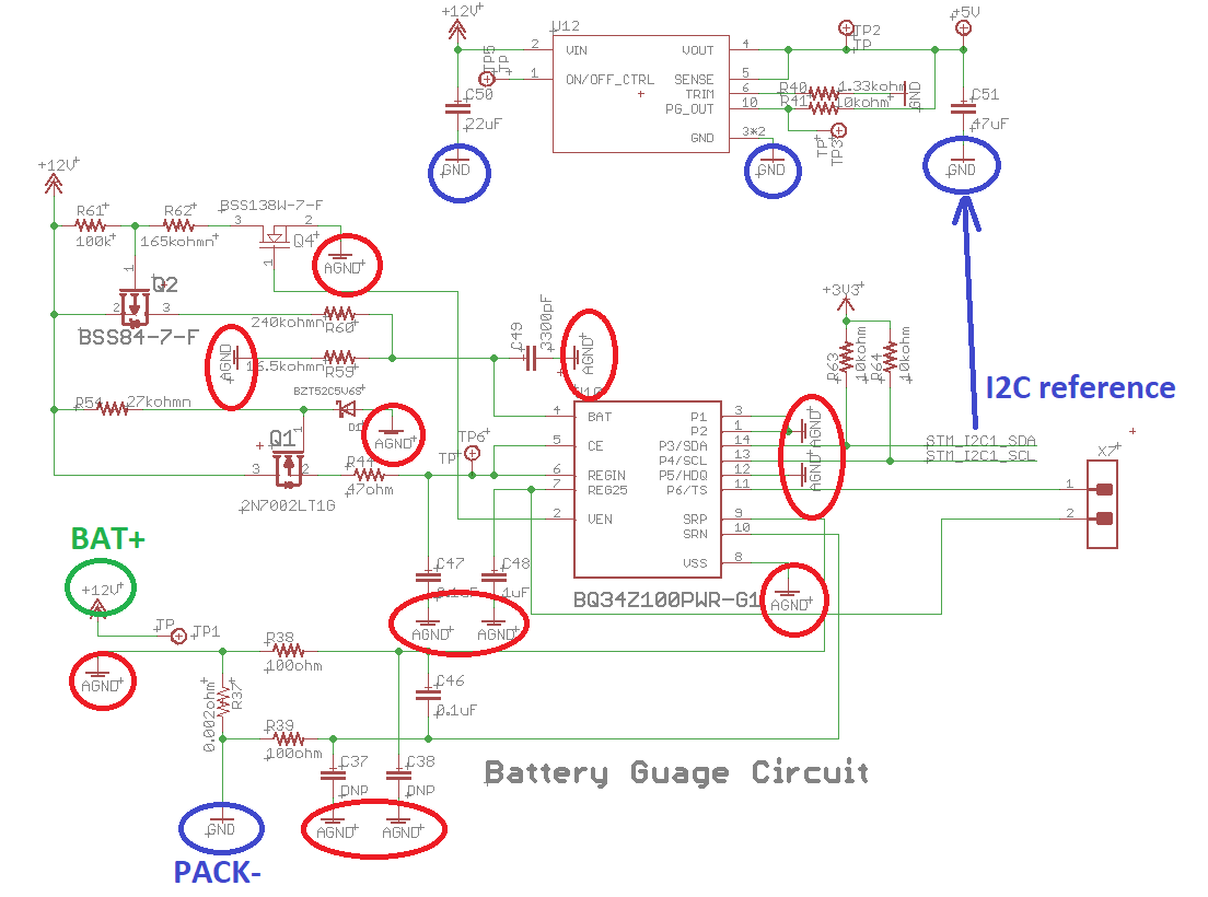
  • To explain further I am attaching my side schematic snapshot that contains this battery guage plus a 5V regulator module. Please note that on my schematic GND means PACK- that is given on TI reference design. My schematic AGND (circled in Red) means the BAT- that is before the sensor resistor, so I am not using this AGND else where like for 5V regulator I have GND (circled in Blue) which is the PACK-, same GND will be used else where. 

    Thanks,

    Muhammad Awais

  • Hi,

    Any comments you guys have on my last messages? I am looking forward to your kind reply.

    Thanks,

    Muhammad Awais

  • Hello Muhammad,

    I suggest following the EVM recommendation. The grounds you are referencing just differs on the sense resistor. In this case it is 2 mOhm.

    Thanks