This thread has been locked.

If you have a related question, please click the "Ask a related question" button in the top right corner. The newly created question will be automatically linked to this question.

BQ25710: Current setting not working correctly

Part Number: BQ25710

Dear all,

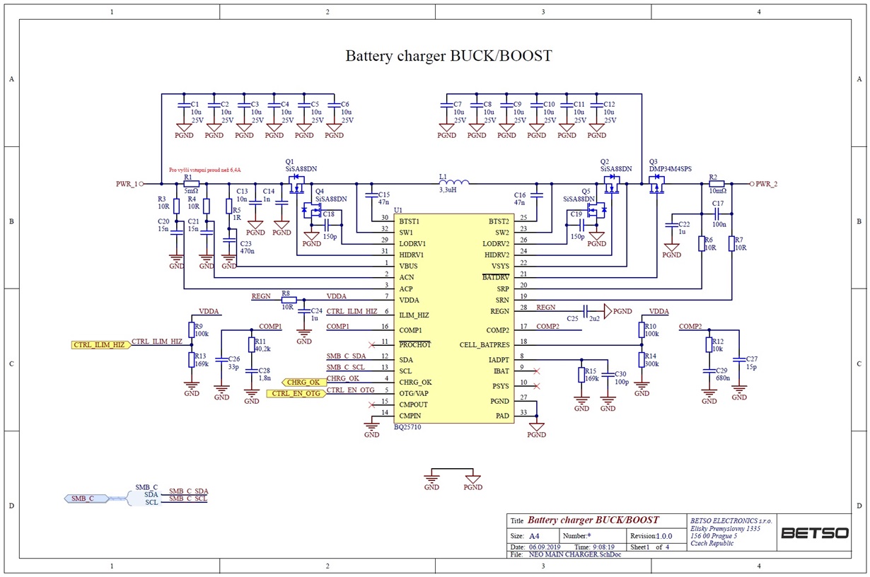
We are working on universal external battery charger in our device using your BQ25710 battery charger device. I attach the schematics. We need the circuit only for external battery charging, not for VSYS power supply. So the battery is connected to PWR_2 and power source to PWR_1.

The problem is, that we are not able to precisely control the charging current Ichrg. E.g.: we set Ichrg to 256mA, but it is 577 mA and if we set the charging current to 512mA than it is 932mA.

What we observed is, that if we have 14V power supply with e.g. around 0.5V ripple than this ripple is also on SRP and SRN inputs to BQ25710. With multimeter, we can measure correct voltage between SRP and SRN pins, that equals currents mentioned above (577mA and 932mA) but I'm not sure, if BQ25710 can measure it correctly. In ADCIBAT registers there are lower current measurements, that doesn't match with multimeter measurements. We tried to put also decoupling capacitors 0.1uF on SRP and 0.1uF SRN to ground, but it didn't help.

Please could you advice where could be the problem?

Please could you advice also correct IC setting for intended functionality or provide some more detailed technical documentation?

Some hint could be, that Q2 burned couple of times during the tests, also Q5 and R2 burned once from some reason.

Perhaps we should operate BQ25710 without the BATFET if we don't need the VSYS to be regulated?

Thank you,

Kind Regards

Pavel Vavra

  • Hi Pavel,

         BQ25710 can't operate without BATFET right now. I suspect the charge current accuracy issue has something to do with stability around PFM mode. Below is my finding on the schematic, please modify the hardware to see if there is any improvement. 

        1, Since you are using 3.3uH inductor, not only IADPT resistor should be changed. Please only change COMP2 compensation resistor R12 value accordingly:

            R12= (3.3uH/2.2uH) * 10K= 15K

        2, Input current sensing R1 should be 10mohm instead of 5mohm. The filter parameters should also follow TI reference design shown below. R3/R4 =5ohm; C20/C21= 33nF.


        3, Minimum output capacitance should be 7*10uF MLCC+ 1*47uF POSCAP. This is important to improve the stability and reduce output ripple.

    Regards


  • Hello Shishuo,

    thank you for you fast reply and good recommendations.

    Add 1) Great point, we overlooked this.
    Add 2) We had 10mOhm soldered and problems were also with that sense value. In the target design, we want to use 5mOhm input sense resistor in order to be able to use higher than 6.4A input current, as we will often work in Boost mode and want highest charging current possible. Do you thing this would not work? We didn't find any note in datasheet that would not permit to lower this sense resistor value.
    Add 2) Regarding R3/R4 =5ohm; C20/C21= 33nF filter, we will try this values as well, but we put values from datasheet typical application section, where 10ohm, 15nF are mentioned.
    Add 3) We will increase output capacitance, also great point here, thank you so much.

    We will try the modifications and will put some additional information. If there would be any further suggestion it would be highly appreciated.

    Thank you again,

    Kind Regards

    Pavel Vavra

  • Hi Pavel,


        BQ25710 is not able to support 5mohm input current sensing for sure.

        After you make the hardware change if it works normally, you can try 8mohm current sensing to increase input current limit but you should be aware of the potential oscillation risk of reducing input current sensing resistance.

    Regards

  • Hi Shishuo,

    we are in progress of making new prototype. We discovered another error in our schematic in C29 where we put 680nF instead of 680pF. We will test new version of schematic next week. We hope BQ25710 will be working as expected then. If it is so, then input sense resistor lowest possible value is 8mOhm, right?

    And also, could you please provide me some example of initialization code for basic operation without any special feature turned on, just for setting of charging current and charging voltage? To eliminate possible error in initialization.

    I will post the results here.

    Thank you very much

    Pavel

  • Hi Pavel,

        Right, minimum input sense resistor is 8mohm. But customer should be aware of the potential oscillation risk of reducing input current sensing resistance.

        Our user register default setting should be good for initialization. 

    Regards