Hi,
Good day. I am using this Boost IC for Vout 3.3V, 40mA for the input voltage range from 1.5V to 3V. But it is not working as per the Webench simulation report. The Schematic circuit, BOM and waveform for various nodes are given for your reference. Kindly provide the solution to solve this issue.
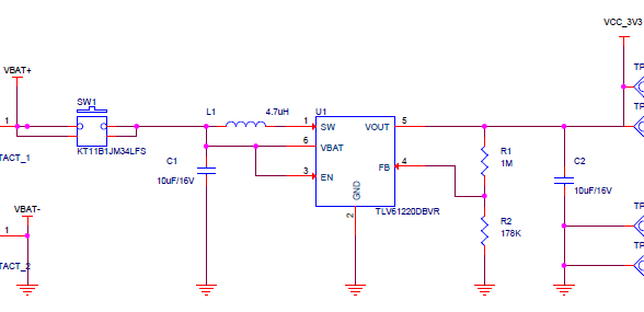
| C1, C2 | 10µF ±10% 16V Ceramic Capacitor X5R 0603 (1608 Metric) | Murata Electronics | GRM188R61C106KAALJ |
| L1 | FIXED IND 4.7UH 1.1A 160 MOHM | TDK | MLP2016H4R7MT0S1 |
| U1 | Boost Switching Regulator IC Positive Adjustable 1.8V 1 Output 220mA (Switch) SOT-23-6 | Texas Instruments | TLV61220DBVR |
| R1 | 1 MOhms ±1% 0.063W, 1/16W Chip Resistor 0402 (1005 Metric) Thick Film | Vishay Dale | CRCW04021M00FKEDC |
| R2 | 178 kOhms ±1% 0.063W, 1/16W Chip Resistor 0402 (1005 Metric) Automotive AEC-Q200 Thick Film | Vishay Dale | CRCW0402178KFKED |
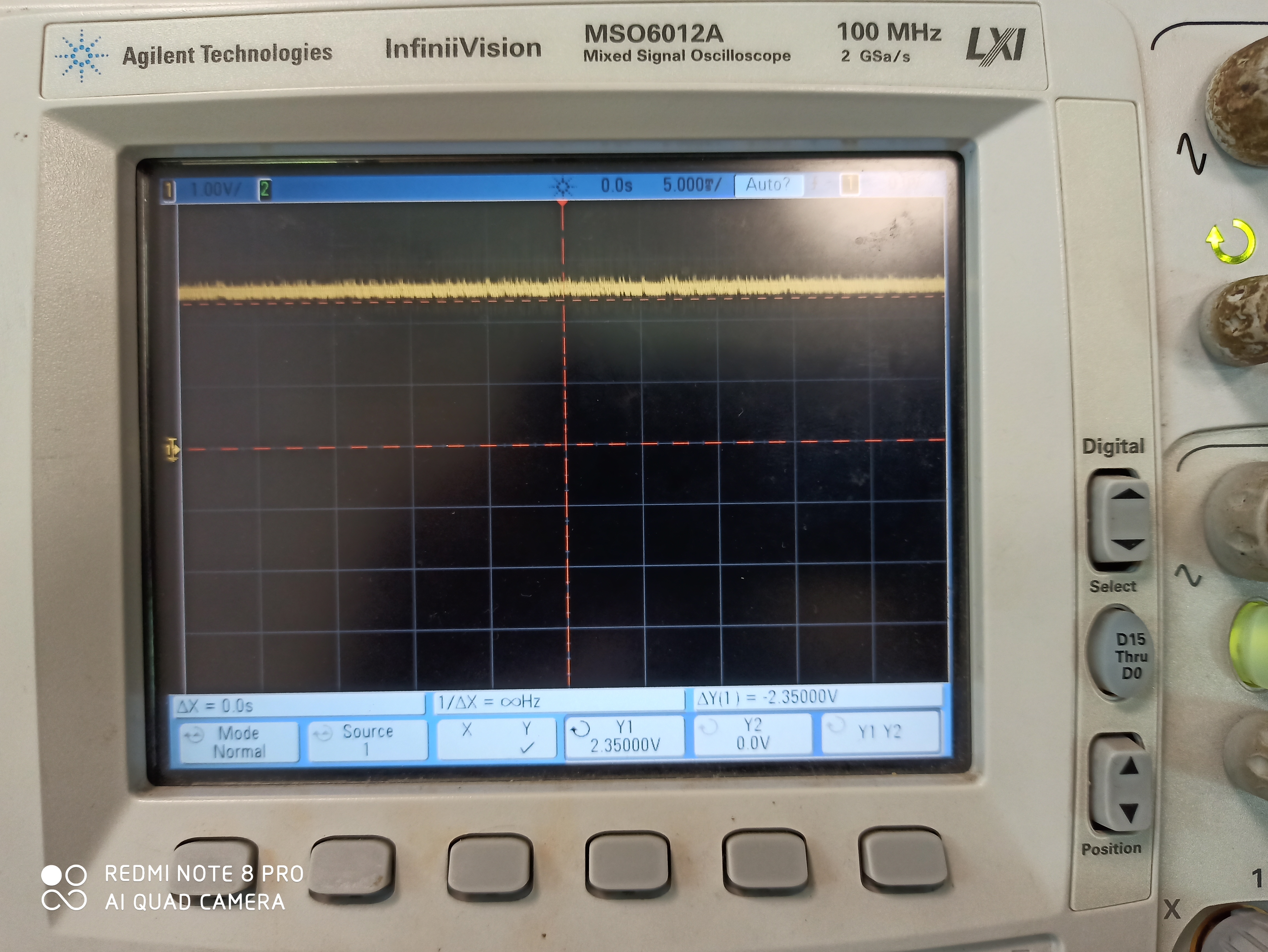
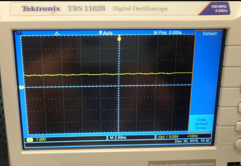
1. Output voltage graph at 3V input (Vout 2.4V instead of 3.3V)
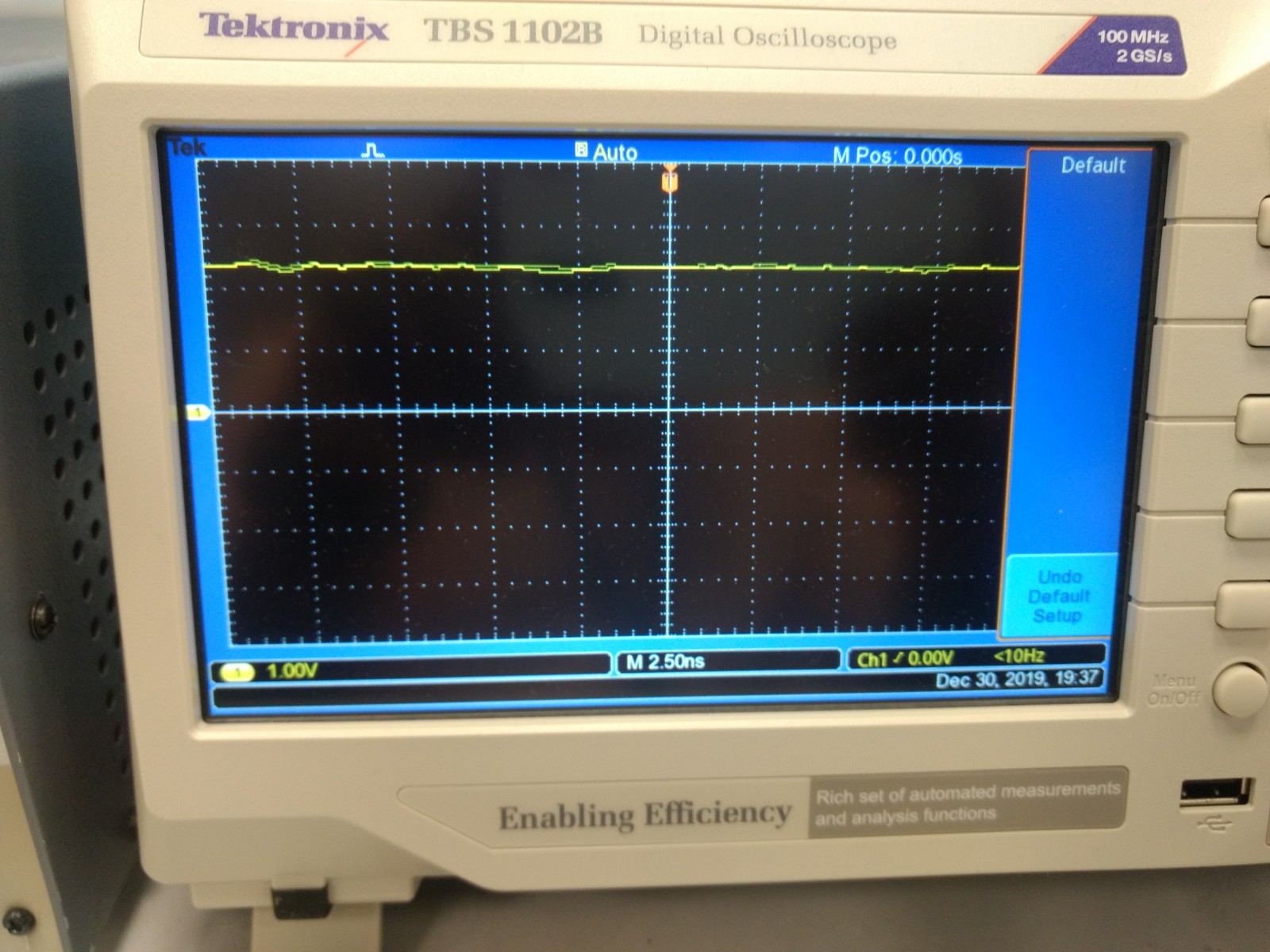
2. Feedback voltage graph
Thanks,
Siva