This thread has been locked.

If you have a related question, please click the "Ask a related question" button in the top right corner. The newly created question will be automatically linked to this question.

TPS2662: Device fails test with -18V on Output. TPS26625

Part Number: TPS2662

Hello,

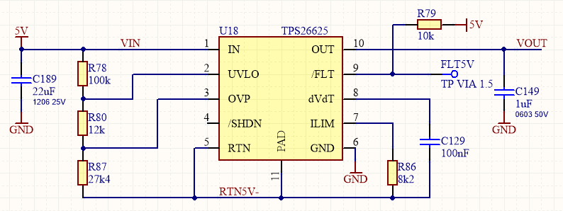
The TPS26625 is used in the following circuit with +5V on the input:

In the data sheet 9.3.4.2 Output Side Reverse Polarity Protection; it shows with 24V IN and -24V OUT that the device can survive this condition.

To test I have applied -15V for a short time to the output and works OK (red = OUT, blue = IN 5V):

-17V was also OK, but then increasing to -18V the power supply giving -18V went into current limit (1A). It looks like the TPS26625 is conducting because the 5V supply drops to 3V and OUT on the TPS26625 is at 1.5V:

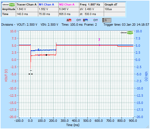
After the -18V supply has been removed the TPS26625 OUT pin is cycling between 4.5V and 5V at 1Hz (1070ms):

The device seems to be damaged and replacing it with a new part get normal operation. Repeating the test at -18V results in another failure. However the data sheet shows applying -24V on the OUT pin without problem.

Why is the part failing in my test? Any help appreciated.

Thanks, Ken

  • Hello Ken,

    Can you please share a waveform for VIN, VOUT, FLT and RTN Pins (Preferably Zoomed In) when -18V is applied on output?

    Was the -18V applied instantly on output or  increased slowly?

  • Hi Lokesh,

    Thanks for suggesting to zoom in. Now I can see what's happening. I am applying the -ve voltage instantly and there is a transient overshoot due to cable inductance. Here with -10V on OUT the overshoot is -45V (red = OUT, blue = RTN, 5us/div):

    Fitted a SMDJ26CA bidirectional TVS between OUT and GND and now survives -18V on OUT. Overshoot clamped to -33V:

    And also survives -24V on OUT:

    So I should have paid more attention to section 11.1 Transient Protection in the data sheet. Thanks for pointing me in the right direction!

    Ken