This thread has been locked.

If you have a related question, please click the "Ask a related question" button in the top right corner. The newly created question will be automatically linked to this question.

TPS23751: Phy IC damaged when plug/unplug POE

Part Number: TPS23751

Hi,

Phy damaged issue is resolved by putting Bidirection TVS on Differential line and Unidirectional TVS on Each line Tx+/- and Rx+/- at phy side.

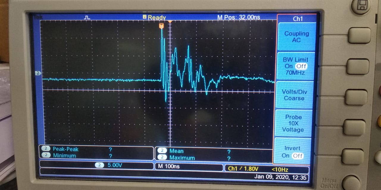
Above is test at POE switch (PSE) adapter (48V/2A) with earth connection but without earth  up to 40V for 0.5us-2us are comes when plug /unplug event of POE connector (J4). that is the new issue for us.

so now without earth why up to 40v are comes on differential pair at the time of plug/unplug of POE connector (J4).

Please note that up to 40v are comes without any protection diode connected on differential pair it is reduce up to 15-20v when connected TVS diode.

Attached waveform is differential line RXP-RXN with tvs protection and with Earth connected in POE switch.

Note- without earth means no earth connected in POE switch (PSE) adapter.and earth means earth connected in POE switch adapter.

Reply-

Hello,

So to understand, there is a 40V spike on the PD on J4 VDD-VSS when you plug it in when there is no earth ground. But if the PSE is connected to earth ground, there is no spike? And if you add the TVS diode the spike is reduced to 15-20V. Is that causing any damage? 

Am I understanding, if you connect earth ground to the PSE and the diodes there is no problem, is that correct?

For new issues, please create new threads. Thank you. 

Regards,

Michael Pahl

Hi,

PSE is connected to earth that time also spikes are comes between 10-15V(without TVS).

and when if we add the TVS diode the spike is reduced to 15-20V this cause also damage but very rare (reduced freq.)

and if we connect the earth to PSE and connect TVS diode that time no damged phy.

My aim of explanation is that without earth connect to PSE, PHY damaged at the present of TVS diode.freq is less but it is damaged.

Regards,

Irfan

  • Hello Irfan,

    irfan memon said:

    when if we add the TVS diode the spike is reduced to 15-20V this cause also damage but very rare (reduced freq.)

    and if we connect the earth to PSE and connect TVS diode that time no damged phy.

    My aim of explanation is that without earth connect to PSE, PHY damaged at the present of TVS diode.freq is less but it is damaged.

    Is there a reason you cannot connect the earth to PSE and connect TVS diode? My understanding is there is no damage when it is connected to earth and the TVS diode is connected, or am I missing something? Why can you not use this?

    Also, what power level is this spike? Can you share the ratings we need to meet for this phy? 

    Additionally, since the spike is a lower voltage, can you implement a filter to protect the phy?

    If this post answers your question, please indicate so by marking this thread as resolved. Thank you.


    Regards, 


    Michael P.

    Applications Engineer

    Texas Instruments 

  • Hi,

    We are using earth but if Earth is open at some location in that case our phy will damaged.

    we are use LAN 8740-Phy IC

    Yes ,we can implement filter to protect phy please suggest to us 

    Regards,

    Irfan

  • Hi,

    Please suggest filter to protect phy.

    as per recent observation phy damaged when plug/unplug poe approx 50-100 times plug/unplug cycle even with connected to earth on PSE adapter.

    Regards,

    Irfan

  • Irfan,

     Why is the poe plug/unplug 50-100 times? Is this going to be typical for the system application?

    this is sounding like a phy problem, I suggest you contact their support team. 

    If this post answers your question, please indicate so by marking this thread as resolved. Thank you.


    Regards, 


    Michael P.

    Applications Engineer

    Texas Instruments 

  • Hi,

     Phy damaged in 04 devices out-off 50 devices during testing  in our production at testing time.so for simulate issue at our office  we have plug/unplug .

    after that we found that phy damaged during plug/unplug.

    Now please suggest us the solution.

    Regards,

    Irfan

  • Irfan,

    Have you tried filtering out the spike? what power level is this spike?

    Looks like the maximum voltage input for the phy is 3.3V. What voltage does your design try to push through?
    I highly suggest putting a clamping diode before the phy to protect it against a voltage spike. 

    I also highly suggest contacting the Phy support team for further assistance. 

    If this post answers your question, please indicate so by marking this thread as resolved. Thank you.


    Regards, 


    Michael P.

    Applications Engineer

    Texas Instruments 

  • Hi,

    Yes, we have used filter circuit at POE input side after Bridge rectifier D42 220E,2A FB at VDD and VSS 2.2nf cap at input, 2.2nf at output side as per PMP23154 .

    We have also used clamping diode at differential line(S43LCC0403)and Uni dir. diode (ESD8351HT1G) at each Common mode diode .after that Voltage clamp at 4.5 to 5V .see attached waveform .

    also added spikes waveform at plug/unplug event.

    As per above observation there are two types of waveform 1) 1us -3us 2)10 to 100ns

    also measure the power -64w-100w @10-30ns

    Also contact with PHY support.

    Regards,

    Irfan

  • Irfan,

    Looks like the max voltage rating on the device is 3.6V so please design the clamp and filter so that the voltage does not exceed this. 

    If this post answers your question, please indicate so by marking this thread as resolved. Thank you.


    Regards, 


    Michael P.

    Applications Engineer

    Texas Instruments 

  • Hi,

    Device working voltage is 3.3V. can you tell me that we had selected tvs diode is right or wrong selected ? we have used S43LCC0403 bi directional diode on diff line i.e 1)TXP and TXN 2) RXP and RXN.

    also used  ESD8351HT1G single endded diode on all 04 pins i.e TXP,TXN,RXP,RXN.

    (http://ww1.microchip.com/downloads/en/DeviceDoc/00001987A.pdf )  5.1 Absolute Maximum Ratings*   ,

    Positive voltage on input signal pins, with respect to ground (see Note 2) ............................................... VDDIO + 2.0 V    it means 3.3+2V=5.3V  sustain at phy pins am i right or wrong


    Regards,

    Irfan


  • Irfan,

    The diode seems fine. As long as the diode is clamping the voltage under the max rating. 

    If this post answers your question, please indicate so by marking this thread as resolved. Thank you.


    Regards, 


    Michael P.

    Applications Engineer

    Texas Instruments