This thread has been locked.

If you have a related question, please click the "Ask a related question" button in the top right corner. The newly created question will be automatically linked to this question.

Difference between DCM and PFM

Other Parts Discussed in Thread: LMR23630

Hello,

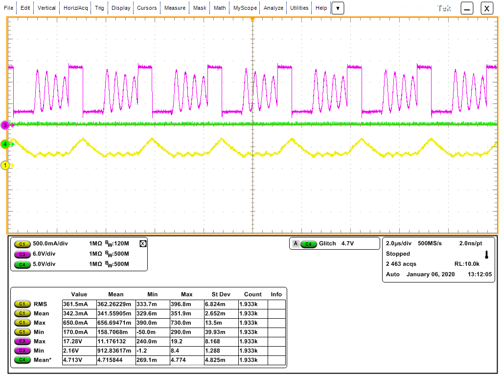
I tested with LMR23630 EVM board and I could get the result like this when the Iout = 0.1A at the light load.

The minimum peak Inductor current to enter the PFM Mode is 300mA, so the yellow graph(Inductor current) shows PFM Mode control.

But, the yellow graph is also showing DCM(Discontinuous Conduction Mode).

What is the difference between DCM and PFM?

The Pink Graph is the voltage sw node. Why the voltage is ringing when LS switch is off?

Thank you

  • Hello. PFM mode modulates switching frequency to improve light load

    DCM just describes the converter tristating (turn off both FETs) to avoid inductor current going negative.

    For a converter with little inudctor current ripple you may go into PFM mode prior to going discountinuous, but often the case is you go discontinuous before you go into PFM mode.

    SW node rings due to LC resonance of package and FET parasitics and is characteristic of bucks that are operating in DCM.. 

  • Hi Garam,

    The yellow graph is inductor current, it obviously has DC offset round 250mA, so actual peak is about 350mA. 

    B R

    Andy