This thread has been locked.

If you have a related question, please click the "Ask a related question" button in the top right corner. The newly created question will be automatically linked to this question.

LM26420-Q1: LM26420-Q1 EMC- Conducted emissions from components/modules – current probe method

Part Number: LM26420-Q1
Other Parts Discussed in Thread: LM26420

Hello

        Our power systerm : Vin=5V,output:3.3V/500mA,1.2V/500mA.  Part number:LM26420Q1XSQ/NOPB.

       Test method : Conducted emissions from components/modules – current probe method ,lever 4

       The PCB Layout and schematic reference to the datasheet.

      The test resault 

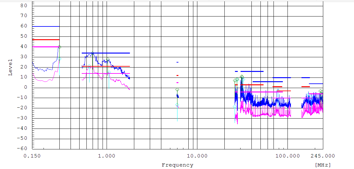
   The number of 2.2M frequency exceeds level 4 standard。

  Otherwise ,I use LM26420Y (550kHz)instead of  LM26420X(2.2M).The resault is follower.

       LM26420Y is better than  LM26420X.

Question:

① Is LM26420Y  Qualified With AECQ-100?

② What measures can be improved the EMC?

  • Hello Zanlin,

    There is no 550kHz version of LM26420 available which has been qualified for Q100. As you already figured out with the measurement data you are showing above your input filter/input capacitor network works better for the lower (switching) frequency. To get lower peaks in the 2MHz range with the LM26420Y you need to adjust your filter accordingly. As a first step I would suggest to check the impedance characteristic of the input capacitors you used. Due to parasitic inductance they may have already high impedance at 2MHz. 

    Best regards,

    Juergen

  • Hi Juergen,

            Our products are used in the automotive.We focus on environmental reliability,,so the product should have be Qualified With AEC Q100.Thanks.

            Could you tell me how much  the impedance characteristic of the input capacitors should be at 2.2MHz?Thanks.

    Zhuzanlin

  • Hi Zanlin,

    You can try to match it to the values you see at 550kHz since at 550kHz it appears to work. Bu I think it may not be as easy as just changing capacitors. Parasitics of your PCB design may significantly contribute to the impedance characteristic. There also will be a difference when measuring common mode or differential mode currents. 

    Anyway, I think you are trying to analyze/optimize something which is not applicable. Are you planning to design a product supplied with 5V through a cable connection routed through the car with the LM26420 directly connected to this cable?

    Best regards,

    Juergen