This thread has been locked.

If you have a related question, please click the "Ask a related question" button in the top right corner. The newly created question will be automatically linked to this question.

WEBENCH® Tools/LM3481: LM3481 with coupled inductor

Part Number: LM3481

Tool/software: WEBENCH® Design Tools

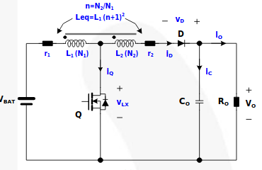
For a design with a high boost factor (4-5) I'm considering to use an LM3481 with a coupled inductor: drive L1 with the switch and put the coupled L2 electrically in series towards the output to multiply the output voltage.

Can Webench / Power designer calculate the compensation capacitors and resistor for this configuration if choose L to be the coupled inductance L1 *( 1 + (N2/N2)^2), assuming that the L1 (N1 turns) and L2 (N2 turns) have a high coupling factor?

A related question: Webench always configures 165 uF output capacitance for these devices, independent of the design parameters. For a 120V boost with a small output current (100-200 mA) that leads to a low ripple but results in a physically large solution with a large current loop which is not ideal from an EMI point of view. Can I reduce that capacitance and include an LC filter or does that lead to stability issues?

  • Hi M Hesselberth,

    Thanks for reaching out with your question and for considering the LM3481.

    Unfortunately WEBENCH will not support the compensation calculation and selection for the configuration that you are describing. Can you please sketch out the configuration you are considering just to make sure that we are on the same page?

    To help find the right configuration I have a few questions.

    1. Does the application require isolation?

    2. What is the minimum input voltage required?

    Thanks,

    Garrett

  • Hi Garrett,

    I'll insert a picture of the configuration I have in mind.

    Isolation is not required but I don't rule out a transformer. They are hard to find for my parameters though: Vin = 22-26V, Vout = 120V, Iout_max = 200mA.

    Thanks,

    Marcel

  • Hi M Hesselberth,

    Another solution is to design a boost converter to operate in discontinuous conduction operation to achieve the required step-up ratio. Take a look at this reference design. Taking this approach would save from having to do a complicate magnetic design.

    http://www.ti.com/tool/PMP21781

    Let me know what you think about this approach.

    Thanks,

    Garrett