Other Parts Discussed in Thread: TPS61253A, TPS61022, TPS61023
1The TPS61256 is used as a 5-V power supply with up to 600-mA output current, but when loading is about 100mA , The TPS61256'S output is always about 2.7v by scope .but when remove the loading ,the TPS61256'S output become right ( 5v )
Result When loading is above 100 mA ,the softstart of TPS61256 stopped the rectifying switch, which protect the TPS61256? ( see page 17 )
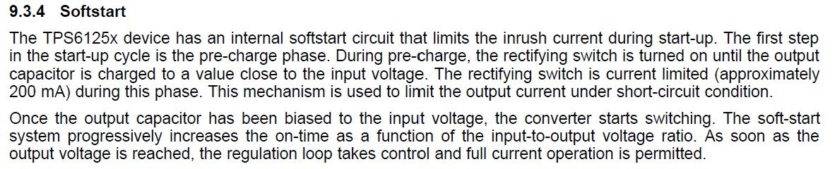
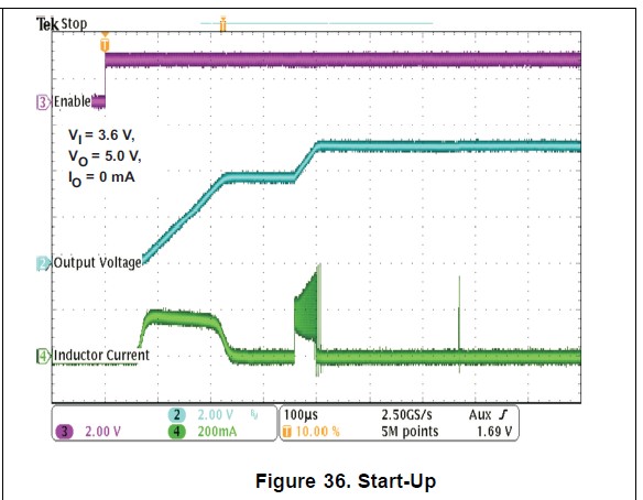
The TPS6125x device has an internal softstart circuit that limits the inrush current during start-up.
capacitor is charged to a value close to the input voltage. The rectifying switch is current limited (approximately
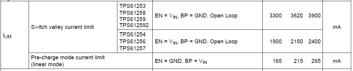
200 mA) during this phase. This mechanism is used to limit the output current under short-circuit condition.
.
so The TPS 6125* cannot be used for boost circuit ?