This thread has been locked.

If you have a related question, please click the "Ask a related question" button in the top right corner. The newly created question will be automatically linked to this question.

TPS2663: TPS26633 auto retry not working?

Genius 12865 points
Part Number: TPS2663

Hello Team,

The e-fuse is supplied with at 24V supply. Ilim is set to 2.6V ,VOV to 15.7 and Plim to 100W. The schematic is in the following:


Fault resistance R223 is removed.

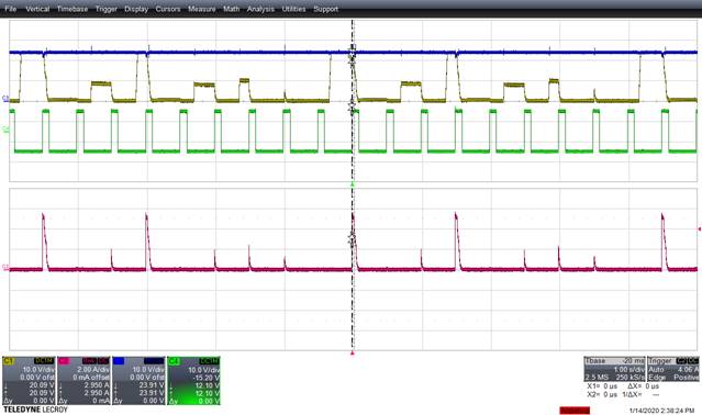
I made a test with the device loaded with a 4 Ohm resistance. As expected the device enter auto-retry mode and continue to assess the presence of a short-circuit. This is shown in the next figure where in red is the output current and in yellow the output voltage. Till here everything works as expected.

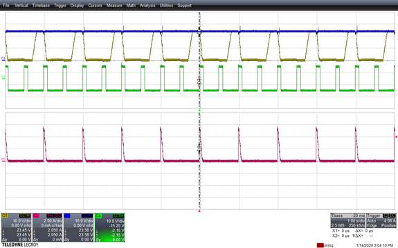
In order to verify that the device can effectively detect the end of the short-circuit condition, the load resistance is pulsed (figure) in a asynchronous manner.


In the figure three different situations are depicted.

1)     No short circuit is present , hence current doesn’t rise and output voltage raises to 24 V. The load commute and short circuit is detected.

2)     Short-circuit is still present during autoretry. This fall back in previous expected behavior.

3)     During autoretry, no short circuit is present. However the device output voltage don’t rise to 24V, but to some intermediate level.

I actually can’t explain point 3.

In datasheet, you say that the UL certification for the device is still pending. Do you have an idea on when you can confirm that the device will be UL certified?

Thanks and Best Regards,

Hans

  • Hi Hans

    I am not able to exactly figure out which portion of the second scope shot refers to condition. 3

    Can you please highlight the portion of the scope shot for the third condition that you have mentioned. It will be good if you can share FAULT pin behavior along with output voltage and  load current.

    Thanks & Regards

    Abhijeet

  • Hello Abhijeet,

    please see my comments in the picture below. FAULT pin is not monitored. The current peaks after short is removed occur because the short is pulsed.

    Best Regards,

    Hans

  • Hi Hans

    Thanks for the explanation.

    I was going through  schematic and device is configured with

    C(dV/dT) = 10nF

    COUT: 2.2mF

    If I use these values in the In-Rush current equation given in datasheet (Page 18, equation 1) then the inrush current comes around 10.5A. 

    The device current limit is set to 2.64A (6.8k resistor on ILIM pin). As current limit is set to 2.64A, my guess is device may be entering in current limiting when it tries to recover from short circuit condition.

    I will try to modify TPS26633 EVM as per customer schematic and will capture device performance in next couple of days.

    Meanwhile can you please check the performance with following conditions

    1) C(dV/dT): 220nF, COUT: 2.2mF

    2) C(dV/dT) : Open, COUT: 2.2mF

    Thanks  & Regards

    Abhijeet

  • Hi Abhijeet,

    I performed the requested measurements. I added the power supply measurement (blue) that is steady at 24V and the load gate control (in green). The load is active when the gate is high.

    In the when Cdvdt=10ns (standard case) the measurement is the following:


    The previous measurement is confirmed. Removing the dvdt capacitor we get to the following measurement:


    The problem is still present. By adding 220 nF dvdt capacitor the problem looks solved.


    Still I don’t understand the intermediate voltage in the first two cases and why the problem would be solved by limiting the DvDt and why we can get three different behavior in case 1 and 2.

    Thanks and Best Regards,

    Hans

  • Hi Hans

    Thanks for performing these experiments.

    I am little surprised by C(dVdT)= open case. I  checked the performance today with 2mF output capacitor at my end and with C(dvdT) open and I could see device was recovering from output short circuit condition every time without issue.

    I will share scope captures with C(dVdT) value of 220nF and C(dVdT) = open with you by Thursday (Tomorrow being holiday in India).

    Thanks & Regards

    Abhijeet 

  • Hi Hans

    Please see attached waveforms which I captured on EVM. You can see output is recovering from short circuit condition.

    C(dVdT) = 220nF, COUT: 2.2mF, ILIM: 2.5A

    C(dVdT) = Open, COUT: 2.2mF, ILIM: 2.5A

    In order to reproduce the behavior that you are seeing i reduced the ILIM to 1.5A and I could see the performance similar to what you are seeing. I captured input current waveform with output voltage to see if device is going into thermal regulation and you can see highlighted portion in below scope shot where input current is tapering which indicated thermal regulation (similar to figure 22 of TPS2663x datasheet)

    I think device is getting heated either due

    1. High inrush current forcing device into thermal regulation at second recovery cycle

    2. Device hitting the current limit regulation when I set lower current limit (where device will try to maintain current for certain time and that heats up the device).

    This forces device in thermal regulation loop and the maximum timeout from thermal regulation loop is 1.25s.

    I increased output load turn OFF time to 2s and i could see device recovering correctly after every time. I also tried reducing the time duration/duty cycle of short circuit pulse and that also helped (as it helps with reduced self heating during start up).

    You can try these two things at your end and let me know your finding.

    Please click "This resolved my issue" button if this post answers your question

    Thanks & Regards

    Abhijeet