This thread has been locked.

If you have a related question, please click the "Ask a related question" button in the top right corner. The newly created question will be automatically linked to this question.

BQ24773: BQ24773 is module going to shutdown beyond the 2W load ..?

Part Number: BQ24773

Hello TI,
               We are working on BQ24773, previously design module setup for testing which is working on 5W load properly with 5.5V/ 2A wall adapter but with new design we observe some unexpected behavior of setup it's going to shutdown beyond the 2W load...?

We use 0402 passive components packages on board and try make it compact, got all reference voltages properly on board but its not going to source required current as per the previous design, please anyone can help me to resolve this issues  

please take look of both schematic for the reference, please correct if i am missing anything New_Design.pdf
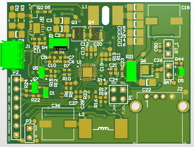
 Old_Design.pdf

thanks and regards'

Rahul Surawase 

  • Hey Rahul,

    Are there any differences between your previous schematic and component selection versus this new design, besides reducing the size to 0402 packages?

    This is especially important for the capacitors used on the board, as you may likely have to either reduce the capacitance, reduce the voltage rating, or change to a lower temp co. (i.e. X7R to X5R) whenever you go down in package size. 

    Do you have the new and old BOM, and the old schematic?

    Regards,

    Joel H

  • Hello Joel,
     

    I attached both old and new schematic above
     

    we also try to same circuit components which we used on old design, means we replace all 0402 capacitor with which we used on old module(0805)  as per  you mention above point operating voltage and temp issues but not found any difference in system behavior, why the module not taking load beyond the 2W...?

    there is any suggestion on this 

    i am attaching new design module BOM and old module schematic please check once
    New_BMS_Design_BOM.pdf6761.Old_Design.pdf

    Thanks and regards, 

    Rahul Surawase

  • Hey Rahul,

    I reviewed the old schematic and new schematic and not much seems different apart from the ACDRV and CMSRC resistors being cut in half, and lowering the ACDET threshold. 

    I cannot tell from the schematic, but were your MOSFETs changed at all? Since I only have the new BOM, I would need to clarify.

    Also, are there difference in the output capacitors? 

    In your new BOM, you have C31, C32, C33, C34, C35, C37 which are 22uF caps but they don't appear on your "New Design" schematic. Where are these capacitors located? Were they on the previous design?

    Can you provide your register settings between your old and new design?

    And most importantly, can you provide a waveform of each design (Old and New) operating with 2W load? This will help compare the two behavior. If the New Design cannot achieve 2W, please take both Old and New waveforms with P(SYS) load = New Board max load.

    Please show the PHASE node, SYS node, VCC node, and IBAT or ISYS. 

    Regards,

    Joel H

  • Hello Joel,

                       There is some issue in Ground looping, test and resolve the our self. 
    Now it's working similar to our master module, Thanks for your valuable time and response Joel

    Thanks and regards, 
    Rahul Surawase