This thread has been locked.

If you have a related question, please click the "Ask a related question" button in the top right corner. The newly created question will be automatically linked to this question.

TPS2H000-Q1: TPS2H000-Q1: Accuracy of current limit

Part Number: TPS2H000-Q1

Hello,

for a new project at 30V, I have to drive 2 outputs with a maximum current of 300mA and I want to try to use TPS2H000-Q1.

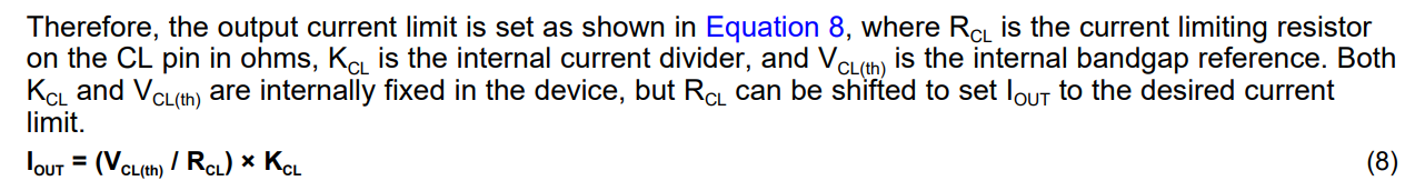
I noted there's the CL (Current Limit) pin, where I can connect an external resistor to ground. This pin can be connect directly to ground to high current limit.

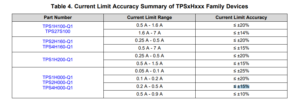
1) In the data sheet it's written the internal current limit when CL is connect to ground and the minimum value is 1A and maximum value is 1,6A. This range is very wide. In this way, I can not have a precise maximum current value to design the power supply.

2) Because I want 300mA maximum current on load, I want to use an external current limiter using an external resistor between pin CL and ground. But I read the accuracy is up to +/-25%... is it correct? If it's correct, is it mean the current limit is between 225mA to 375mA. But which is the reason of this bad accuracy?

3) do I need to use an external resistor for current limit?

Thank You and Best Regards
Federico Battaglin

  • Hello Federico,

    I would recommend reading http://www.ti.com/lit/an/slva859b/slva859b.pdf if you have not already done so as it has a lot of really good information about how the current limit is setup on the device.

    At your load voltage of 300mA you are looking at ≤ ±15%. Refer to the table below from the above application note:

    If you want to limit the current to 300mA as reference you have to use the external resistor for the current limit. Specifically with this device you will use the following equation (taken from the above app note):

    You will need an RCL value of 800Ω. Without a resistor the nominal current limit for the device is a range from 1.0A to 1.6A, with a nominal value of 1.3A. This is useful for when there does not have to be an explicit current limit on the load, however conditions such as short-to-groun want to be accounted for. 

  • Dear Timothy,

    thank You for your reply and for indication of that application note.

    Yes I just saw and read it.

    Some questions:

    1) why so this wide range of accuracy? 15% is a not small value! In my mind, 5-10% is ok...but not 20-25%

    2) seeing the table 7.5 "electrical Characteristics" of the data sheet of TPS2H000, why the Icl(int) has minimum at 1A and maximum 1,6A? Which is the "min", "typ" and "max" conditions? Are due to temperature or the difference between each chip?

    3) seeing the table 7.5 "electrical Characteristics" of the data sheet of TPS2H000, the "current sensing accuracy" and the "external current limit accuracy" are defined in the test condition of Vvs is 13,5V. Which is the"min", "tyP" and "max" values when the voltage is double (Vvs=27V)?

    4) why so difference between CH1 and CH2 in the figures 16 to 24?

    Thank You and Best Regards

    Federico Battaglin

  • Fredrico,

    1) The accuracy variations you see at higher output load currents versus smaller load currents is due to the inner workings of the current limiting circuitry. While these accuracies might not be in line with a device such as a current controlled load switch they are competitive as far as high side switches. The way that I look at this is that these margins can be factored in holistically when it comes to the whole application design. Figure 6 does a good job illustrating this in the referenced application note:

    Essentially what this is saying is that if you are setting your current limit to a certain accuracy range that you should make sure that your upstream power supply will operate properly at the worst case margin and not droop/degrade.

    2) The reason for this variation isn't so much to do with temperature but rather to do with the fact that the internal reference used for the internal current limit is not trimmed device-to-device.

    3) The load voltage has a very minimal effect on the current sense accuracy. We can dig up a "typical" value for this voltage profile, however if you use the minimum and maximum values at the voltage scoped in the datasheet you will have the most robust design. 

    4) This has to do with the coordinates of both channel's FETs in the device and the length of the bond wires. A longer bond wire will lead to different properties of the FET which accounts for the variations you see on the graphs.