This thread has been locked.

If you have a related question, please click the "Ask a related question" button in the top right corner. The newly created question will be automatically linked to this question.

LM66100: LM66100

Part Number: LM66100

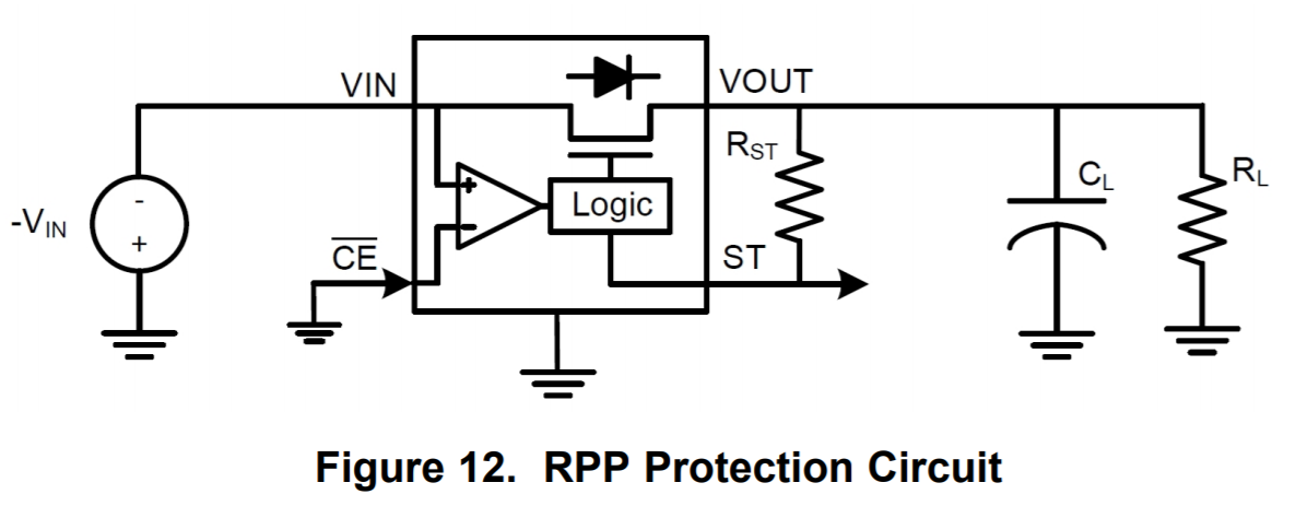
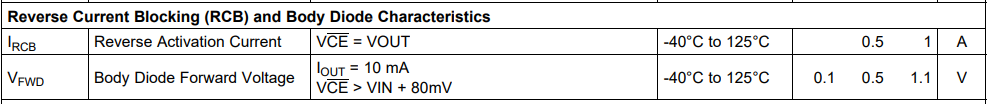
What is the electrical characteristic, Ircb, Reverse Activation Current listed in Section 6.5 of the LM66100 datasheet?

  • Mike,

    To elaborate here more on what exactly is going on in the diagram and what the  IRCB means in the design let's look at the reverse current blocking diagram again:

    Essentially when the LM66100 is on the internal FET is going to look like a resistor with a resistance of RON. The RON value is spec'ed in the datasheet for several different input voltages.

    The value of VOFF that you see under  the Comparator Chip Enable (CE) section of the datasheet is the voltage difference that is needed between VOUT and VIN that needs to be present in order for the LM66100's reverse current blocking logic to activate. This is detected in a reverse current setup as the VOUT pin is connected to the active low CE pin's comparator logic. At the point where VOUT is detected, the datasheet parameter of IRCB is simply the current going across the FET's equivalent resistance RON.

    Take the worst case of 125°C at 5V for example. In this case the RON value is 120mΩ. The worst case VOFF scenario in this case is 80mV. Dividing the VOFF value by RON we get an  IRCB value of 0.667A. This is essentially the value which is being described in the datasheet for IRCB as a range over all spec'ed voltage and temperature conditions. 

    There is a very good chapter about reverse current protection in the 11 Ways to Protect Your Power Path eBook that TI provides. I would recommend taking a look at it if you have not already. Please do not hesitate to reach out if you have any questions.