This thread has been locked.

If you have a related question, please click the "Ask a related question" button in the top right corner. The newly created question will be automatically linked to this question.

ISO5852S: Protection of the gate driver IC during over loading

Part Number: ISO5852S

Dear sir,

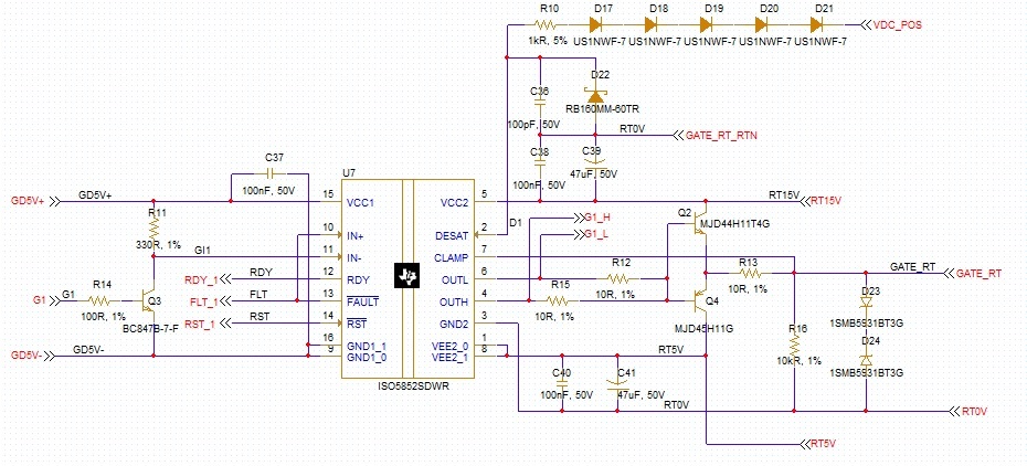
we are using ISO5852S for our inverter gate driver. Our circuit is given below.

When the IGBT was failed (desaturation was disabled) gate - emitter was damaged. 1SMB5931BT3G was damaged. 

It damages the ISO5852S driver also. Short-circuit was happened between the pin numbers 1, 5, 6 & 7.

Is it possible to protect the ISO5852S during gate - emitter short circuit condition. 

Thanking you.

Thanks & regards,

Rajasekaran.

  • Hi Rajasekaran,

    It looks like your GND2 reference for the blanking capacitor (GATE_RT_RTN) is different from the GND2 terminal (RT_0V). These two should be the same reference point. Your GATE_RT_RTN point may be floating. Is GATE_RT_RTN connected to RT_0V someplace else in your schematic?

    Regards,

    Audrey

  • Dear sir,

    The GND2 reference for the blanking capacitor and GND2  terminal are connected in schematic using net labels (RT0V). 

    still we faced this issue. Kindly let us know the possible solution to protect the IC during over loading condition. 

    Thanks & regards,

    Rajasekaran.

  • Hi Rajasekaran,

    Thank you for pointing that out, I did not see the net reference.

    What is the status of Q4? Is it also damaged? Are there other components that were damaged, and did you test the driver using a continuity test on the board or did you remove the chip?

    I would recommend a different protection diode with higher peak pulsed power rating, such as the SMAJ series TVS diodes in the place of D23/D24. There are internal clamping diodes within the IC from OUTH/OUTL and CLAMP to VCC2 to hold the gate at slightly above the voltage supply to protect the IGBT gate during a short circuit. 

    Additionally, since you are using a BJT buffer you must include a resistor/capacitor from OUTL to VEE2, and shown in Section 2.1.7 of this reference design for driving paralleled IGBTs. Otherwise you will have a very large transient when turning off the IGBT which will result in high dI/dt and VCE overshoot because you are not implementing soft turn off through Q4.

    Regards,

    Audrey

  • Hi,

    Q4 was not damaged. Only D23 &D24 are damaged.


    we removed the chip from the board and tested. Pins  1,5,6 & 7 shows continuity. 

    we will try to use the soft turn off using external capacitor and resistor. also we will try to use the TVs diodes.


    thanking you. 

    thanks & regards,
    Rajasekaran.

  • Hi ,

    do we have any formula to calculate Resistor and capacitor values for soft turn off?

    thanking you.

    thanks & regards,

    Rajasekaran.

  • Hello Rajasekaran,

    Please see this E2E post with link to the TI Training which discusses this feature.

    Regards,

    Audrey