This thread has been locked.

If you have a related question, please click the "Ask a related question" button in the top right corner. The newly created question will be automatically linked to this question.

BQ25600: Design Guidance on use

Part Number: BQ25600
Other Parts Discussed in Thread: BQ27220, BQ25601, , BQ25601D,

The bq25601 does not pinout the BATSNS pin. Implementing the bq27220 coulomb counter will require a sense resistor between the positive battery terminal and the bq25601 charger BAT pins. Ideally, the BATSNS would connect directly to the battery to properly read the battery voltage and effect proper charging of the battery. This eliminates any parasitic trace impedance which when using the coulomb counter is the sense resistor (0.010 ohms). What is TI's recommendation?

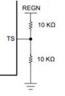
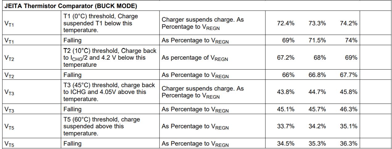
In the datasheet, it states that the BQ27220 will make a better measurement of SOC with an external thermistor attached to the battery. The datasheet indicates connecting the thermistor from the BIN pin to VSS with no additional resistors. The BQ25600D also requires a thermistor but a recommended pull-up and parallel resistor are recommended for proper operation. Is it possible to eliminate these two resistors required by the BQ25600D assuming these resistors are integral to the BQ27220 or the integral signal condition is adequate for both parts?

Is there a reference schematic diagram using both parts

Thanks

  • Hi,

    1. BQ25600D has BATSNS pin.

    2. If BQ25600D TS pin is not used, it is ok to connect 10kohm from REGN to TS and another 10kohm from TS to GND for normal operations.

    Thanks,

    Ning.

  • My questions haven't been adequately answered.

    1.) The BQ25601D is offered in an alternate package but the BATSNS pin is missing. 
    Please advise is we can use the BQ27220 and a 10mohm sense resistor with this part
    Without the BATSNS pin the BQ25601D cannot measure the actual Battery voltage during charge
    Please advise regarding how we can implement the BQ25601D with the BQ27220 

    2.) We want to us the temp sense pin on the BQ25600D to monitor the battery temperature during the cycle but
    Your response seems to indicate that this pin is not used at all. Is that the case?
    Assuming we can use the TS on the BQ25600D then we would also like to us the BIN pin
    on the BQ27220 also and share the same Thermistor.  Please advise a method to do so.

  • Please review additional input

  • This remains an issue for us - HOW to raise this for more support?

  • Hi,

    1. BQ25601D is designed without BATSNS. This is charger support. Please submit another thread for bq27220 gauge support on how to work with a charger without BATSNS.

    2. When using the charger alone with the gauge, user just needs to connect the thermistor to the gauge only. It is not necessary to connect the thermistor to the TS pin of the charger. Just connect 10kohm from REGN to TS and another 10kohm from TS to GND for BQ25600D normal operations as shown below.

    Thanks,

    Ning.

  • 1.) Your answer regarding the not connecting the thermistor to the charger (using default 10k up/down) seems to defeat the charge temperature protection built into the charger.  IT seems prudent to have the thermistor connected to the charger provides a mechanism for the charger to reduce the charge profile when the battery gets "HOT".  Please explain your reasoning for the suggested implementation.

    2.) How and where  do we submit a question regarding the BATSNS  when using the BQ25601D with the BQ27220.  This is a lengthy process to get what seems to be recommendations if and how to use these two components together 

  • Can we escalate this to a product specialist that understands the use of these part in the same design? 

    Thank you

  • Hi,

    1)  When using the charger alone with the gauge, the thermistor should be either connected to the gauge or connected to the charger, but not both because the charger and the gauge have different specs on the thermistor connection. The BQ25601D has below TS pin specs, while the gauge may have different specs. The BQ25601D follows JEITA charging profile (9.3.7.5 JEITA Guideline Compliance During Charging Mode). Connecting the thermistor to either the gauge or the charger will protect the battery charging based on certain temperature profile. If you choose to connect the thermistor to the gauge, you may connect the TS pin of BQ25601D per the circuitry above.

    2) Gauge usually requires current sensing resistor. Please follow the gauge d/s.

    3) When you submit a new e2e thread with subject "bq27220 questions", the thread will be automatically routed to the gauge support and someone will respond shortly. Since the current thread with subject "BQ25600: Design Guidance on use", it was routed to us - the charger support.

    Thanks for your understanding,

    Ning.

  • My understanding is that the Charger has the responsibility to properly charge the battery and needs to measure the battery voltage for the proper charge profile.  The BQ25600D has a separate BATSNS pin to make that measurement eliminating any parasitic trace resistance.  Adding the BQ27220 requires a 10 millohm resistor in series with the battery to measure current (an obvious parasitic resistance).  I was hoping that the BQ25601D component has an adjustment to compensate for the voltage drop across the sense resistor and any other parasitic resistance.  Since the BQ2560x group is responsible for the charger, I don't understand why you are suggesting the the BQ27220 group should answer the question.

    I see from the chart provided that thermistor thresholds vary for the two components (Not sure why).  However the charger needs the temperature to properly charge the battery and the "Gauge needs a thermistor to proper calculate charge. I'm not sure how fixing either is optimal.  You seem to indicate that fixint the charger TS input may be the best overall solution.   Seems like the thermistor inputs of these two parts should have been coordinated or at minimum the algorithms of each part been coordinated so that a single thermistor could be used.

    -R

  • Hi,

    As mentioned earlier, the thermistor should be either connected to the gauge or connected to the charger, but not both. It is ok to connect the thermistor to the TS of the charger and not to use the thermistor function of the gauge.

    If any assistance is needed for BQ27220, please submit a new thread and the gauge support will help.

    Thanks,

    Ning.

  • Ning

    In three replies you have answered similarly. However you haven't fully addressed my questions.  We want the operate the charge circuit with minimal processor intervention.  According the the BQ25600 the thermistor is required so the BQ25600 can adjust the charge profile if the battery gets hot so it seems this connection is necessary.  The BQ27220 needs the thermistor for accurate battery charge gauging.  Please advise technicallly why I would eliminate the thermistor connection for either device.

    My other question has never been addressed.  The charger (BQ25600) has a BATSNS connection to compensate for parasitic resistance between the battery and the charger.  This has nothing to do with the BQ27220. Now I need to add a 10 millohm sense resistor in the path between the charger and the battery obviously behaving like parasitic resistance.  The BATSNS input provides a mechanism for the charger to properly monitor the Battery voltage during charge. We would like to use the BQ25601 charger but it doesn't provide the BATSNS input which seems required as discussed.  Can you address how the BQ25601 is to be used properly with a 10 millohm resistance between the charger and the battery.  

    -R

    If you cant answer these BQ25600 questions please advise someone in the Bq25600 group that may be able to fully address the questions

  • Greg,

    As mentioned earlier, it is ok to connect the thermistor to the BQ25600 only and let the BQ25600 control if thermistor temperature is out of normal range. Please refer to Fig 28 on the d/s for typical application.

    For BATSNS, referring to the BQ25600 d/s, no 10mohm resistor is no needed.


    For BQ25601, 10mohm resistor should not be connected neither. Please refer to Figure 28. Power Path Management Application on the d/s for typical application circuitry.

    Gauge team,

    Could you please help to answer what shall a user do if no thermistor is connected to BQ27220?

    Thanks,

    Ning.

  • Hello Ning,

    We recommend thermistor connection, otherwise gauge will not measure correct temperature.

  • Hi Greg,

    I apologize for the confusion. I will start with some background.  First, the chargers are essentially power supplies with complex state machines and analog feedback loops while the gauges are micro-controllers using ADCs and digital logic.  Each require different skill sets for technical support.  Second, the gauge makes more accurate voltage, current and temperature measurements compared to the charger.  Therefore, most of our customers who use both charger and gauge write host software to make continuous gauge measurements and then send I2C commands to change the charger operation if necessary.  But the chargers have to be able to work standalone. I explain in more detail below. 

    Regarding which IC gets the thermistor, to conserve power, the battery-powered gauge only powers up its thermistor periodically and compares to its internal reference.  However, the charger, with input power, constantly powers its thermistor to a different voltage and compares to its internal reference.  Therefore, there is currently no way for the charger and gauge to use the same thermistor.  When installed on the battery pack, many of the gauges, including the BQ27220, can be configured to use their internal die temperature to estimate pack temperature instead of using an external thermistor.  Specifically the bq27220 can be configured via the OpConfig A[TEMPS] bit. Refer to page 22 of the TRM.  Therefore, the charger can use the thermistor and the gauge can provide redundant battery temperature protection.

    Regarding the BAT pin sense/regulation voltage with the gauge's 0.01 ohm low side current sense resistor, you are correct in that the charger regulation will be affected by the voltage drop across the 0.01 ohm resistor.  The charger will exit constant current (CC) mode and enter constant voltage (CV) early because the BAT pin will see a voltage drop = Icharge * 0.01 ohm that pushes it up to VBATREG.  Even without the sense resistor, all chargers enter CV mode early due to PCB trace + connector + pack protector FETs "parasitic resistance" in between in the BAT pin and the battery cells.  A charger with separate, Kelvin BATSNS connection can be used to bypass some of the parasitic resistance.  Once in CV mode, the charger holds it voltage at BAT = VBATREG and the charge current naturally tapers down until it hits the charger's configured termination current, if enabled, or the gauge tells the charge to stop based on its more accurately measured battery current.  

    I hope this helps answer your questions. If I can help further, please post more questions or friend request me in this forum for private follow up.

    Regards,

    Jeff F.

  • Hi Jeff,

    Thank you very much from Richard and myself for your detailed response. The information was very helpful in understanding the issues.

    It would be great to get both of these parts in the same package. Please let us know when it is available.

    Much appreciated.

    Greg