This thread has been locked.

If you have a related question, please click the "Ask a related question" button in the top right corner. The newly created question will be automatically linked to this question.

LP2951-Q1: Fixed 5V and Adjustable 3.3V Output Review

Part Number: LP2951-Q1

Hi team,

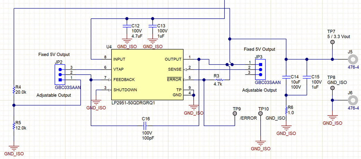
I am designing a power supply with selectable 5V or 3.3V output using LP2951-Q1 and jumpers JP2 and JP3. The input power supply on Pin 8 is 25V, and C14 and C15 are ceramic capacitors. I've read the datasheet and EVM User's Guide in completing this design, so I understand there are nuances with this device.

Please review my schematic below and let me know which changes are encouraged:


Thank you,
Manuel Chavez

  • Hi Manual,

    The design looks okay, except for the output impedance.
    The output capacitance is in series with a 1 ohm resistor.
    This will meet the requirement for stability but will severely affect the load transient response, if there is any in this design.
    I would recommend changing that to a 75m-ohm resistor or somewhere in that range.
    I simulated the impedance of this output capacitance in series with a resistor (1 ohm or 75m ohm) and plotted the two results.
    I used a 10uF model from Murata and a 1uF model from Vishay that I already had on my computer.
    The impedance of the 75m ohm version is significantly better than the 1 ohm version at frequency.

    The hump you see at higher frequencies is due to ESL and resonance conditions between the two capacitors.

    Thanks,

    - Stephen

  • This is great; thanks Stephen!