This thread has been locked.

If you have a related question, please click the "Ask a related question" button in the top right corner. The newly created question will be automatically linked to this question.

TPS25921A: Reverse Current alternative options through topology/components

Part Number: TPS25921A
Other Parts Discussed in Thread: TPS2595

Hello,

A customer wants to use the TPS25921A  and the TPS2595 (in seperate subcircuits, voltage levels are still unknown) and in the design it is still possible for reverse current to occur. However, no significant design changes are unfortunately possible and the TPS25921A and TPS2595 both lack something like the BFET port as in the TPS25924x.

Therefore large changes/options such as using load switches and dual FET solutions are not possible to implement. Are there any ways to ensure there will be no reverse current(or atleast avoid it) by setting up certain component values (criteria)?

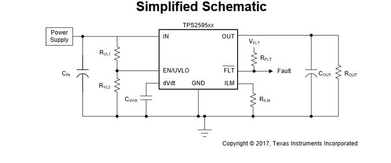
Both will be used in a very similar way like the simplified schematic of the datasheets:

For example, one possible option is Cin >> Cout. Are there any other recommendations similar to this? Or any other minor solutions if there are any are much appreciated.

Thank you.

Assad

  • Hi Assad,

    As you know due to the presense of body diode of internal FET, there is no control on reverse current flow for TPS25921 and TPS2595.

    It is difficult to comment on how to avoid reverse current from flowing unless we know the voltage levels and the exact conditions which cause the reverse current to flow.

    Can you elaborate on how Cin>>Cout helps to reduce reverse current ?

  • Hello Praveen,

    Thank you for your response. The reasoning in this case was to reduce the chance that the output voltage would be larger than the input voltage by having a a small Cout and large Cin. This does not remove reverse current but might help to prevent it. The problem however got resolved as some things have changed, so thank you for your response and time.

    Regards,

    Assad