This thread has been locked.

If you have a related question, please click the "Ask a related question" button in the top right corner. The newly created question will be automatically linked to this question.

UCC28064A: OCP level

Part Number: UCC28064A

Hi TI,

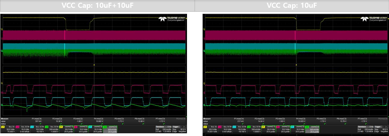
There is a difference in the OCP level depending on the VCC capacitance.

Can you guess this as a problem caused by affecting the noise of the CS pin?

The first waveform is the OCP of the PFC first, and the second waveform is the OCP of the LLC first.

C1: Ouput voltage (LLC output), C2: GDA, C3: GDB, C4: CS

  • Is there a maximum allowed value for the filter applied to the CS pin?

  • Hello Mason,


    Thank you for your interest in the UCC28064A interleaved TM-PFC controller.


    The OCP threshold of the UCC28064A (and of previous controllers in this family) is independent of the VCC capacitance. The fact that the CS signal is different when Cvdd = 10uF compared to 10+10uF must be due to additional noise on Vcs when the second 10uF is added.


    In the 10uF case, you can see that the GDx waveforms are nicely interleaved and the inductor currents tend to cancel so the Vcs signal is low. OCP is not triggered in the PFC stage.


    In the 10+10uF case, the GDx waveforms coincide, the inductor currents add together and the Vcs signal is high enough to trigger OCP in the PFC stage. The controller logic is designed such that after an OCP event turns off both gate drives, they are also restarted simultaneously. The internal phase-locked-loop needs a few cycles to shift the phase back to 180 degrees. However, if the total peak current is still high enough to trigger OCP each cycle, then the GDx will continually restart simultaneously (as shown in the first photo) until the input voltage falls low enough to generate lower peak current.


    The question is why does having 10uF+10uF on VCC result in OCP, when only 10uF does not? I can only guess that somehow additional noise is introduced onto Vcs by the addition of the second 10uF. It may depend on where and how that second cap is placed. Any switching ripple current in the VCC cap may have a different path than with a single 10uF, so that there may be more GND-bounce or some other noise coupling with the second cap. Or, if the two caps are virtually on top of each other, the lower impedance may result in increased peak GND current which may couple to the CS input as increased GND-bounce. Try placing the second 10uF to VCC in different locations to see what affect the placement has on OCP.


    Meanwhile, there is no electrical limit to how much filtering that can be applied to CS. However, there is a practicable operation limit. Certainly, some filter is necessary to block switching noise into CS to prevent nuisance tripping of OCP. The effect of an R-C filter is to delay the rise of the signal which is compared to the OCP threshold. So phase current can rise higher than expected until the threshold is actually reached. Too much filtering will delay an overcurrent signal so much that OCP is effectively prevented.


    If the second 10uF VCC cap must be added for other reasons, and cannot be placed in a way that avoids Vcs noise, then the CS filter must be increased. I recommend that the series R value should stay </= 100ohm.   This is because there is ~150uA bias current coming out of the CS pin, and this bias current flows through the series R which adds a positive offset voltage that tends to cancel the negative CS signal. 100ohm adds ~+15mV, which has a small effect on the -200mV OCP threshold.

    I recommend to increase the Ccs value in small increments to find where the operation behaves normally (no trigger of OCP from noise), then add +20% more for margin.


    The delay will increase the net OCP trigger level of the PFC current. If this becomes excessive due to heavy CS filtering, then increase the sense resistor value as needed to compensate, and bring the OCP level back down.


    Regards,

    Ulrich