This thread has been locked.

If you have a related question, please click the "Ask a related question" button in the top right corner. The newly created question will be automatically linked to this question.

TPS2373-4EVM-758: some questions from measurement

Part Number: TPS2373-4EVM-758
Other Parts Discussed in Thread: TPS2373, TPS2372,

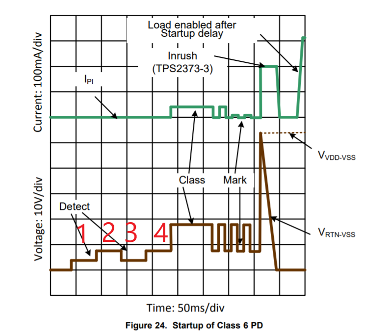
  1. 1.      There is a stage called “Inrush” before PoE startup. According to IEEE802.3bt spec and your TPS2372/2373 spec, there would be limited inrush current for each classes such as 800mA to 900mA for Class 7 and 8. I measured the V-I curve of the TPS2373-4EVM-758 and measured the inrush current around 330mA which is meet the description of TPS2373 spec below. I would like to know why the TPS2373 spec describes the 335-mA inrush current is compatible with all PSE Types, it supposed in the range 800mA~900mA according to the 802.3bt standard, isn’t it?


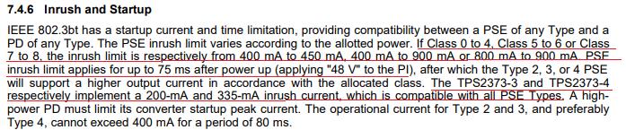
 2. A valid detection signature is to get a 25kohm for Rdetect, which I guess is calculated by the Ohm’s Law via measured V-I curve. It should take few points of measured V-I curve to get Rdetect, the valid detection signature is defined by the Rdetect is in the Range of R-slope as below photograph. I don’t know if I am misunderstanding about the detection method, please advise.


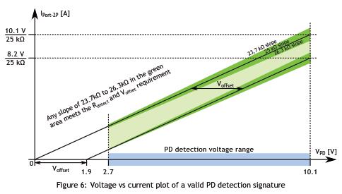
3.Here is the measured V-I waveform on TPS2373-4EVM-758. The Blue one is Voltage of Alternative A, the Yellow one is Voltage of Alternative B and the Green one is the current of I-port. As you can see, this is a whole procedure to powering a Class 8 PD with the CC_DET_SEQ constant as 1, it contains Detection/Connection Check/Classification/Inrush/Startup.

Continuing for the question2, the detection signature is given by Rdetect, which is Vdetect/Idetect, it is hard to judge how the PSE determine it is connected to valid PD by this photograph since current of detection is really quite small, the range of Idetect is around 102uA to 426uA theoretically, and the smallest current scale is 10mA for our current scope, so it barely can’t use this scope to get correct Idetect via this method, the Idetect would just like noise at all.  I wonder if there is another way to determine detection is been process properly.


Thanks a lot!!

  • Hello Bonnie!

    I hope you are well.

    Overall, I think it will help to download the following material over the IEEE802.3.bt standard: https://ethernetalliance.org/wp-content/uploads/2018/04/WP_EA_Overview8023bt_FINAL.pdf

    This is a great summary of the standard. 

    1. The PD has a few options to pass inrush. One option is to limit the current below the standard limit (400mA or 800mA), and this is the method the TPS2372 and TPS237 implement. (Please see Section 7. Inrush, page 33). Therefore the 335mA inrush limit will be correct for all PSE's. 

    2. For detection, the TPS2372 and TPS2373 use a 4 point detection scheme. This way we can get four measurements to determine if a valid detection is present. 

    Typically when looking for a valid detection, the voltage can suffice since the detection and classification can be seen. Additionally it looks like there is a power up, which is good sign. 

    Looking at the scope shots, it looks like the PD undergoes one detection and classification event, and then a second one before being powered up. 

    If this post answers your question, please indicate so by marking this thread as resolved. Thank you.


    Regards, 


    Michael P.

    Applications Engineer

    Texas Instruments 

  • Dear Michael,

    I've downloaded this document before and it's great for a newbie just like me to study PoE BT standard.

    For inrush, I've seen the description you mentioned and it seems the only option which is compliant to the standard. But I still don't know how it works, why the PD limits the Inrush instead of the PSE and why this method make this compliant to standard?
    What is the "Inrush" actual purpose during the PSE powering to the PD?

    For detection, you said the TPS2372/2373 use a 4point detection scheme, which I guess it is the waveform below but more looks like a down stair step instead of power up. Is the waveform must be look like power up as you said? And BTW is there any description about the 4point detection scheme in the datasheet of TPS2372/2373?

    [Looking at the scope shots, it looks like the PD undergoes one detection and classification event, and then a second one before being powered up. ]
    Yeah this is I am curious thing as well, I have no idea why whole the procedure repeat twice instead of once before powered up. Is that acceptable by 802.bt standard?
    From my point of view, powering procedure is under controlled by the PSE, not by the PD. And since the PSE is a third party equipment so I think this is the PSE's problem, not TPS2373's.

  • Inrush is the controlled application of power, to gently switch over from a non-powered state to a powered state. Since the PSE is sourcing the power, it must have some form of current limit. Initially, there is a PSE inrush phase, and then a PD inrush phase. 

    During the PSE inrush phase, there is no particular requirement on the PD. During the PD inrush phase, the PD must:

    "1. Have a total input current less than IInrush_PD (parameter depends on the assigned Class) and have a pairset current less than IInrush-2P on each pairset. 2. Have an input power less than Class 3 (13 W) or the PD’s requested Class, whichever is lower."

    To make our PD's compatible in both situations, we limit inrush current to 330mA, which will pass all phases and all requirements. Does that make sense?

    It is hard to tell what the waveform you are showing is detection or classification. The best place to measure this is on the PD's VDD and VSS. There you will see more clearly the detect and classification voltages, as in figure 24. 

    Yes the PSE can do detection and classification twice, as long as it powers up the PD. 

    If you are concerned about the PSE, you can always try it on another PD. Additionally, you could use one of our PSE EVMs with the GUI to understand what the PSE is seeing. Our software interface shows what the PSE is measuring, which is a good reference.

    If this post answers your question, please indicate so by marking this thread as resolved. Thank you.


    Regards, 


    Michael P.

    Applications Engineer

    Texas Instruments 

  • Dear Michael,

    I see, I am well noted via your detailed explanation which 330mA current limit of PD is make sense, but it also made me confused furthermore. If the PD limits the current as 330mA while PD inrush phase, how could it drawn the power as class8 PD afterward cause the current in normal operation is quite larger than Iinrush if it is a class8 PD, why it won't limits the current as 330mA after PD Inrush phase and get into powering phase? 

    I will take you recommend and check the detection/classification on the PD's VDD and VSS. And I will ask Bonnie to help me apply another TI PSE EVM with GUI to see the bigger picture of whole PoE technology. Thanks for your kindly help and I learning a lot from you.

  • Hello Steven,

    The PSE will apply full power after the PD inrush phase. The IEEE802.3 defines how long the in-rush phase is for both the PSE and PD, so both devices should know how long that phase is. Additionally, the in-rush phase is merely a time between no power applied and full power applied. The fact it has an end implies full power is being applied.

    forum 

    Regards,

    Michael Pahl