This thread has been locked.

If you have a related question, please click the "Ask a related question" button in the top right corner. The newly created question will be automatically linked to this question.

TPS63031: Issues with TPS63031-With Power Saving Mode But one board is working fine another one battery will dry out Soon.

Part Number: TPS63031

Dear Sir/Madam,

Subject: Issues with TPS63031DSKR/design, Battery gets dry out soon.

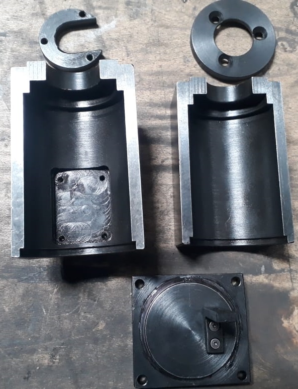
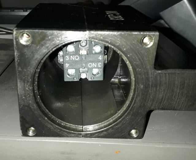
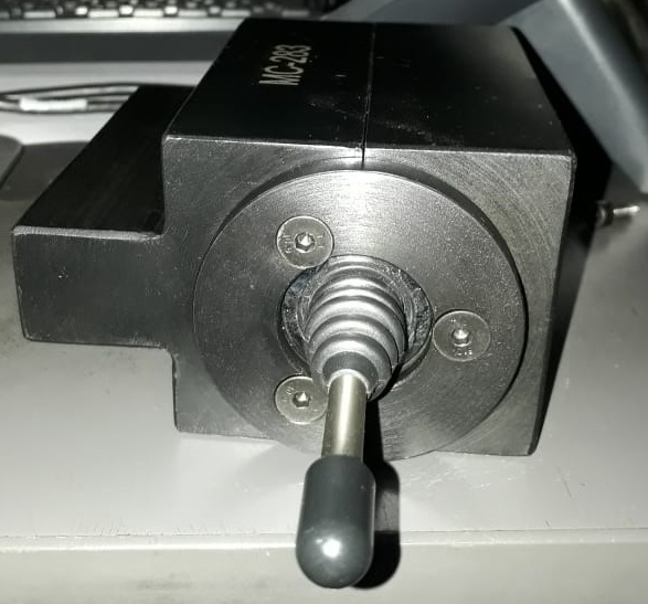
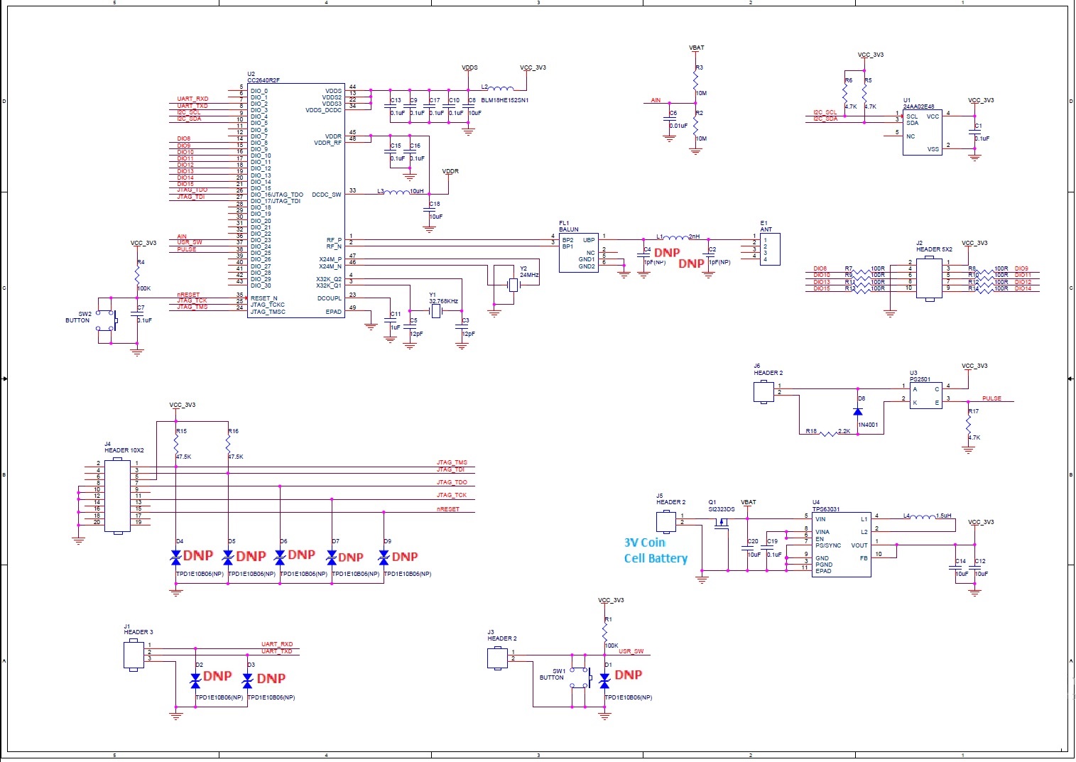
We are using TPS63031DSKR Regulator(U4) for powering CC2640R2FRGZR(U2) as shown in the attached schematic. We are using 3V Coin Cell battery for powering the board.

We are having 3 different Test Cases with the same board and modified schematic for same application (Industrial Machine Automation):

1. Without Regulator- Schematic 1: We have removed the Regulator (U4 as DNP), Directly given Battery Voltage to CC2640R2FRGZR.

RESULT: Battery Backup was Minimum 2days.

2. With Regulator-without Power Saving Mode-Schematic 1:

RESULT: Battery Backup was 1days.

  3. With Regulator-with Power Saving Mode- Schematic 2:

RESULT: Battery Backup was Minimum 2days.


In Case 3 With Regulator-with Power Saving Mode, We put 2 boards for testing, both boards working fine for 7 days. After 7 Days, only one board is working fine with 2 Days battery backup and its still working.

Another board battery will get dry out within one or two hour, but giving Vout is 3.3V. I have removed the MOSFET (Q1) shorted Drain-Source and tested, but issues not solved. I have compared input Impedance and Output impedance with fine board, Output impedance (Vout w.r.t GND) was same for both the boards but input impedance (Vin w.r.t GND) for the fault board was 200 Ohm and in fine board it’s a infinity or >4Mohm.

Kindly help us to find the problem where it exactly and need to solve these issues.

  1. In which part there is a issue? Fault was In the Regulator?
  2. What is the Reason for the issues?
  3. How to overcome this issue in future? Can we really trust the regulator?
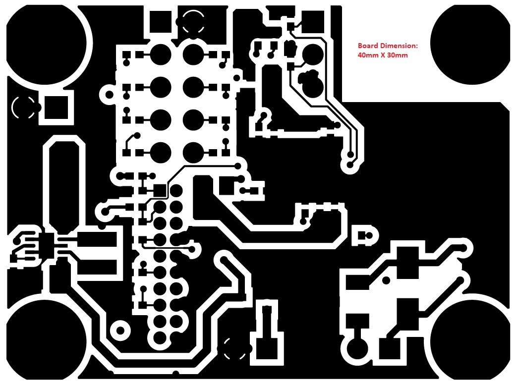
  4. We are planning to go for bulk production due to the requirement, until the issues solved we cant proceed for the production. PFA the Gerber Image, Schematics and kindly confirm is there any issues with the design?
  5. Your advises will be more appreciable for improving product efficiency/design. (4 Layer Board: Inner Layer1 is Ground and Layer2 is 3.3V)

We are Looking Forward to Hearing from You Soon.

Regards,

Naveen K

  • Hi Naveen,

    thank you for using our devices!

    ok, let's try to debug your solution together.

    First question: what is the MCU doing in your test and how much current is it drawing?

    Second question: Have you used a power supply instead of the cell battery to supply your solution and measured the input current to the TPS63031?

    regards,

    Moritz

  • Dear Moritz,

    Thank you for your reply.

    We are using CC2640R2FRGZR as MCU, I have attached the schematic in previous post. Current will be <10mA for fine boards and >20mA for Fault board(Measured in multimeter-not accurate).

    Yes, I tried with power supply, current will be same.

    Assume 2 new batteries, without connection battery voltage will be 3.48V,

    While connecting Battery to the board, battery/input voltage will be 3.43V in Fine board and 2.2 V in Fault board.


    Regards,

    Naveen K

  • Hi Naveen,

    the 10mA/20mA you mentioned is that the input current of your complete solution or just the MCU. At which state of operation is the current flowing?

    Can you measure the inrush current during start up?

    regards,

    Moritz

  • Dear Mortiz,

    Thank you for the reply.

    10mA/20mA current is for complete solution.Because we are having only 3 major components, i.e MCU, Optocoupler and I2C EEPROM, no other component except basic components.

    In faulty board inrush current and continuous current will be same i.e >20mA. In good working boards, its less than <10mA.

    Why in faulty board, input impedance will be 200Ohm and in fine working board it's a infinity(>4 Mohm)?

    Regards,

    Naveen K

  • Hi Naveen,

    can you please switch the TPS63031 from the board with 200Ohms to the one with >4MOhms and vice verca.

    Please measure the input current for each board again.

    thanks,

    Moritz

  • Dear Moritz,

    Thanks for the mail,

    For Swapping of TPS63031 will take some time because we need to outsource outside. Replacing with new IC to faulty board and repeat same test. Is this also fine right?

    Regards,

    Naveen K

  • Hi Naveen,

    that's not the same. Changing the "faulty" unit to the other board and vice versa would show the behaviour of that unit in an 'assumed' good solution.

    If you replace the unit in the 'faulty' board, you will see if the board has an issue.

    regards,

    Moritz

  • Dear Moritz,

    Thanks for the information.

    We will do accordingly and update you the result.

    Regards,

    Naveen K

  • Dear Moritz,

    We are having a new requirement for BLE including TPS63031DSKR board and it should be mounted in the industrial CNC Machine. The Board doesn't have IP68 Sealing Box (even we can't make IP68 Box) and the board will be mounted in the Normal Box. Some times some amount of Coolant/Oil may float inside the box through holes,moisture or some where else.

    Could you kindly suggest any conformal coating for protecting the BLE board from water/coolent/oil in the machine.

    Regards,

    Naveen K

  • Dear Mortiz,

    These are the Box Assembly FYR.

    Kindly Advise.

    Regards,

    Naveen K

  • Hi Naveen : I support reliability on this product. TI has no recommendations on the use of conformal coating where many of our customers add such coating on their own direction.There a different materials out there that have advantages of using as well as potentially introducing other disadvantages.

    One good source as a primer for this topic is a webinar by DfR solutions https://www.dfrsolutions.com/resources/coatings-and-pottings-for-solar-panel-systems.-issues-and-solutions  You can also download their material for reading where page 7 is a good comparison between conventional materials used in the electronics industry for conformal coating. 

    Hope this helps. 

    Allan.

  • Dear Allan,

    Thank you for the information and it will helpful for us.

    We Well Appreciated to Support team. 

    regards,

    Naveen K