This thread has been locked.
If you have a related question, please click the "Ask a related question" button in the top right corner. The newly created question will be automatically linked to this question.
Hi Experts:
i designed a reference voltage for the signal detection with LM431B , the schematic is below:
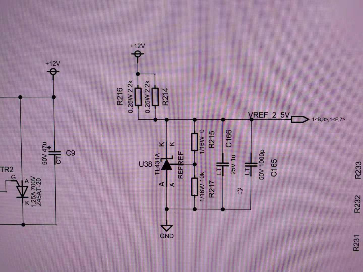
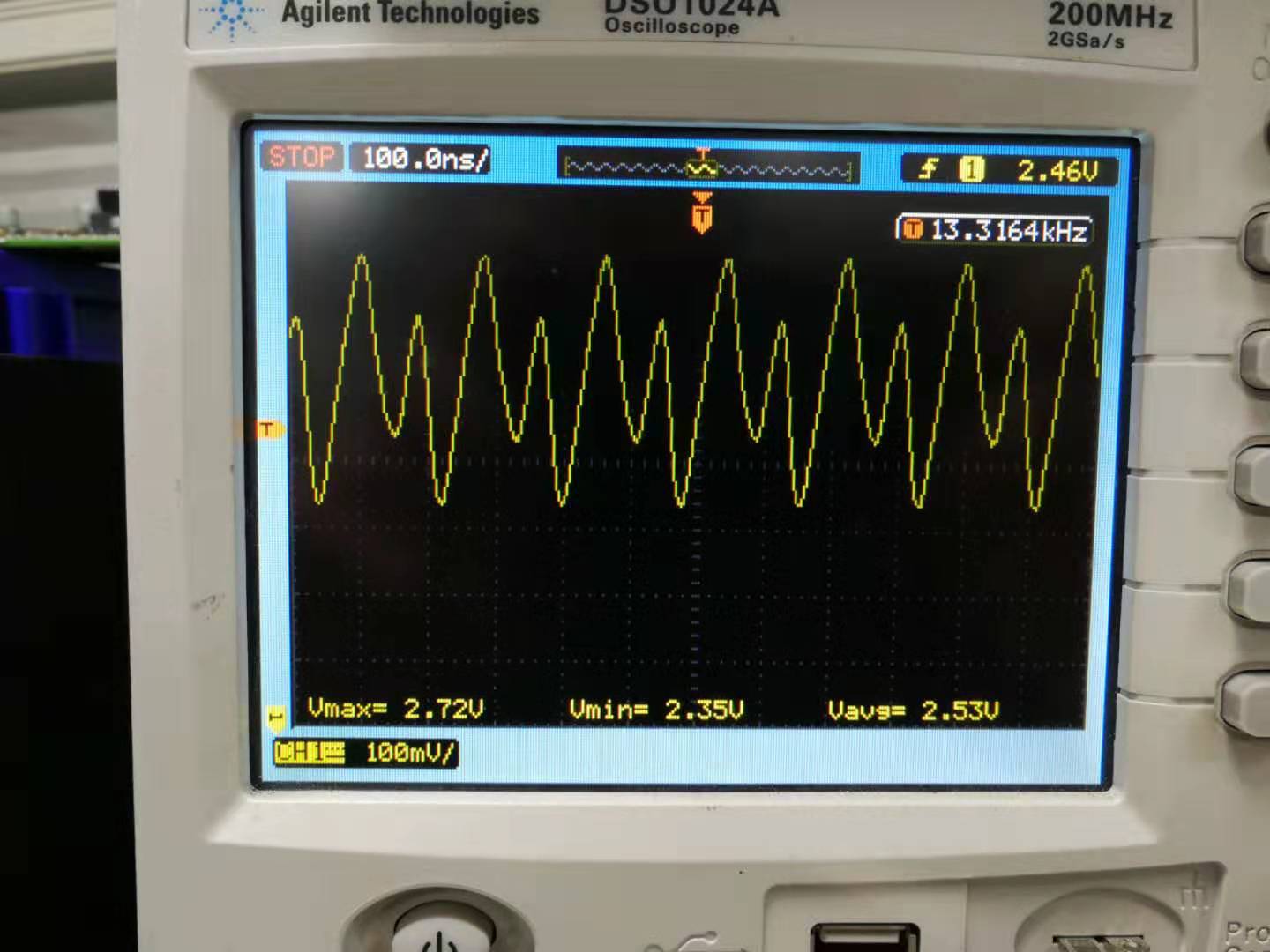
Because the Cload selection could affect the Vout oscillation , i choose the 1nF for the Vout (remove the 1uF ) , however, i still find the Vout oscillation like below:
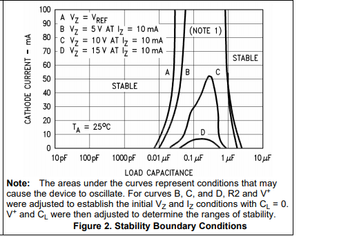
In the description of the datasheet, the Vout is in the stable range:
When i replace the LM431B with the TLV431A in the same circuit , the Vout is stable , no oscillation . Please help me what's the reason , thanks!
Hi Jason,
The stability boundary conditions chart is a typical graph that can vary from device to device and lot to lot.
I cannot recommend to use 1.001uF on the output because it will be in the instability region of both device.
A much smaller much larger cap is recommended. I would check out the app note below to understand stability charts.
While this TL431 might not oscillate, other TL431 can oscillate.
Hi Marcoo:
Thanks for your reply.
Yes, we are currently using the 1nF in the TL431 with no issue . However, i don't know why the oscillation is still existing on the LM431 ?
if this TL431 oscillate and other TL431 can't oscillate , how can we make sure the capacitor is Ok in the mass production stage even it could pass in the evaluation stage.