This thread has been locked.

If you have a related question, please click the "Ask a related question" button in the top right corner. The newly created question will be automatically linked to this question.

BQ24773: efficency tuning / part selection

Expert 1935 points
Part Number: BQ24773

Hello,

we have a battery charger designed around the bq24773. Some design points:

- DC input voltage from the AC adapter is 24V, max 6A.

- The battery pack is 4S (4.2V max per cell), max charging voltage set to 16.8V, max charging current is 6A.

- To minimize switching losses, we choose 600kHz mode in software.

- AC-DET divider is set to turn on at 19.3V

- Maybe I want to upgrade to 8A charging current

Issue: If there is no battery pack connected, the system voltage (Vsys in the EVM schematic) will not always turn on. Same happens if the battery pack is completely empty. Our workaround is to feed DC in directly to our DC/DC for the MCU:

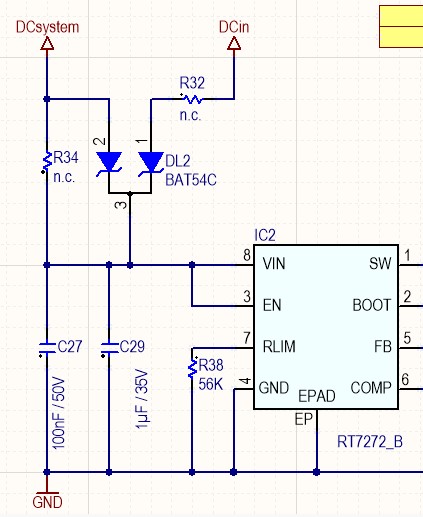
Question 1: Works fine, but I'd like to understand why the bq24773 won't work without battery pack. Should it work?

Tuning. For our prototype we used STN56N3LLH5 (N-channel 30 V, 0.0076 Ω typ., 56 A, 6.5nC, Vgsth 2.5V) and STL30P3LLH6  (P-channel 30 V, 0.024 Ω typ., 9 A), inductor is Würth 74437358022 (2,2µH / 10A / 22A / 9mOhm). I want to replace those three components on the next board. Here is the current schematic:

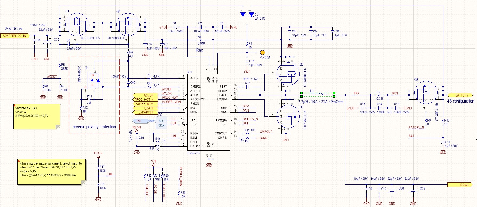
I assume that Q1, Q2 and Q4 are used as switches only, so I'd replace them with MOSFETs with a very low Rdson. For the P-MOSFET maybe a type which can handle a higher current if I want to upgrade to 8A.

I forgot the 10uF on the battery side (C23 in the EVM) that was added as a fix on the board.

Question 2: For Q3 and Q5 I'd choose a MOSFET with a low gate charge first, then a low Rdson next. Is that correct?

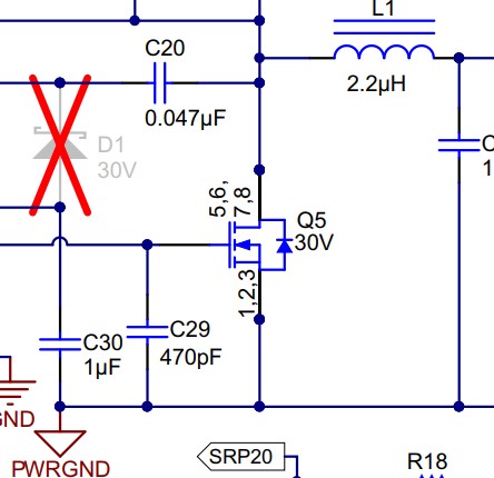
Question 3:The EVM scematic has 470pF (C29) on the gate of the low side FET. Why? The schematic in the datasheet does not mention this capacitor.

When running with a very small charging current (64mA) the bq24773 is the only heat source:

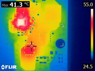
Question 4: Can we do something to reduce the heat generated by the bq24773? Maybe add resistors (10 Ohm?) to the HIDRV/LODRV pins?

These are the two gate drive signals:

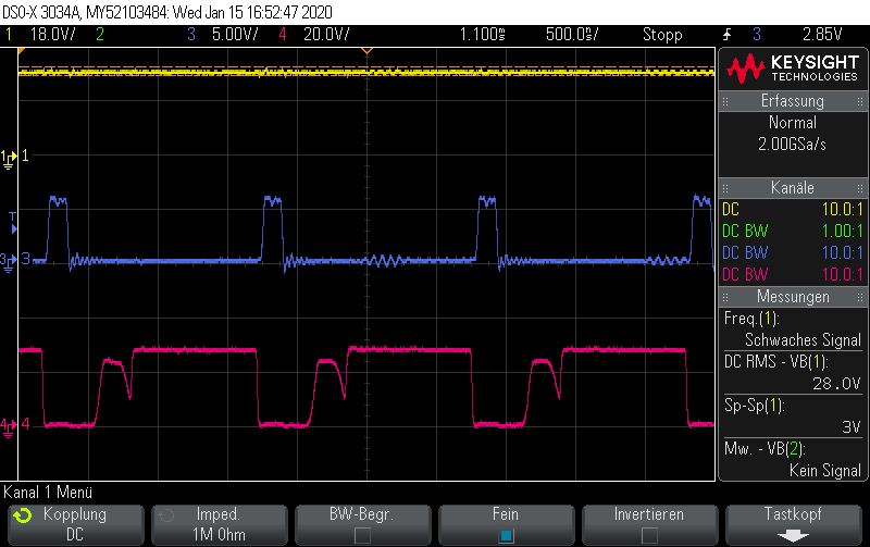
Channel 1: battery current, channel 3: low side mosfet gate drive (LODRV), channel 4: high side mosfet gate drive (HIDRV).

Question 5: Why does the HIDRV signal have this dip? Is it expected? Does is afftect the efficiency? Is my BTST capacitor too small?

At low currents (<1A) we have an efficiency of 92%, higher current still 90% but above 4A it drops below 90%. At 100-120W 10% heat dissipation is quite a lot, so every hint to improve efficiency is welcome.

Best regards,

Lo

  • Hey Lo,

    For 1) It should work without the battery attached. The system voltage should be regulated regardless of the battery voltage. Also your image does not appear. Can you repost it?

    For 2) Your schematic does not appear in the thread. Can you repost it? Without it, I can't tell which FETs Q3 and Q5 are. If they are LSFET in the buck converter, I would focus on the RDSon because of how high your currents are. The conduction losses will take precedence at higher currents. 

    For 3) Without seeing what is attached (you will need to repost all of your images, waveforms, schematics as they did not appear), I assume these are the holding caps on the LSFET. The 470pF on the LSFET is to help prevent a false turn-on of the LSFET during the HSFET turn-on due to the Cgd. We artificially increase Cgs to hold onto the gate.

    For 4) The part number says BQ24733; but you are referring to the BQ24773, correct? Adding resistors to HIDRV and LODRV will make the power loss higher because you effectively reduce the turn-on and turn-off time of the HSFET. This will increase your switching losses. Consider a parallel Schottkey rectifier diode from GND to SW to improve the reverse recover loss, and also consider paralleling HSFETs and LSFETs and finding an even lower DCR inductor.

    For 5) I cannot see the waveform.

    Regards,

    Joel H

  • Hi Joel,

    thanks for the fast response. I had to repost the images, I hope they stick this time.

    Joel Hernandez II said:

    For 1) It should work without the battery attached. The system voltage should be regulated regardless of the battery voltage. Also your image does not appear. Can you repost it?

    I reposted the images.

    I also found out that this issue only occurs on one lab power supply, I have another one which is fine. I'll check for peaks and rise time.

    Joel Hernandez II said:

    For 2) Your schematic does not appear in the thread. Can you repost it? Without it, I can't tell which FETs Q3 and Q5 are. If they are LSFET in the buck converter, I would focus on the RDSon because of how high your currents are. The conduction losses will take precedence at higher currents. 

    Is there a simple way to estimate losses (soemthing besides creating a simulation)?

    Joel Hernandez II said:

    For 3) Without seeing what is attached (you will need to repost all of your images, waveforms, schematics as they did not appear), I assume these are the holding caps on the LSFET. The 470pF on the LSFET is to help prevent a false turn-on of the LSFET during the HSFET turn-on due to the Cgd. We artificially increase Cgs to hold onto the gate.

    Ok, I'll add that one. Is the actual capacity of the capacitor critical?

    Joel Hernandez II said:

    For 4) The part number says BQ24733; but you are referring to the BQ24773, correct? Adding resistors to HIDRV and LODRV will make the power loss higher because you effectively reduce the turn-on and turn-off time of the HSFET. This will increase your switching losses. Consider a parallel Schottkey rectifier diode from GND to SW to improve the reverse recover loss, and also consider paralleling HSFETs and LSFETs and finding an even lower DCR inductor.

    It's the 24773. I'm not sure where I should put a schotty diode for testing.

    Can you explain?

    Best regards,

    Lo

  • Hey Lo,

    Lo2 said:
    I also found out that this issue only occurs on one lab power supply, I have another one which is fine. I'll check for peaks and rise time.

    So your issue is fixed by using a different power supply?

    Lo2 said:
    Is there a simple way to estimate losses (soemthing besides creating a simulation)?

    You do not need a simulation to estimate the efficiency. You need to calculate the anticipated conduction loss through the MOSFETs (based on RDSon and RMS inductor current), the MOSFET switching losses (based on rise times and fall times), inductor DCR loss, and inductor core loss. There are several other losses such as the dead time loss, reverse recovery loss (Qrr) of the MOSFET, and Qoss loss. 

    Lo2 said:
    Ok, I'll add that one. Is the actual capacity of the capacitor critical?


    The capacitor of the capacitor is typically there to make the total effective Cgs capacitance about 1.5-2x higher than the Cgd capacitance. This is more important in FETs where Cgd and Cgs are relatively similar in magnitude.

    Lo2 said:
    It's the 24773. I'm not sure where I should put a schotty diode for testing.

    The Schottky diode is applied between GND and SW. It is in parallel with the LSFET, and in the same direction as the LSFET body diode. It is meant to take the role of the MOSFET body diode. It improves both the reverse recovery loss and and dead time loss. 

    Regards,

    Joel H

  • Hi Joel,

    I got some new MOSFETs today with low Rdson (1mOhm @10V) and mounted them to the PCB replacing Q3/Q5.

    Joel Hernandez II said:
    I also found out that this issue only occurs on one lab power supply, I have another one which is fine. I'll check for peaks and rise time.

    So your issue is fixed by using a different power supply?

    It works with one (beefy) power supply. The other one (24V/5A) does not power it up.

    Now I'm testing with the actual charger used in the field (24V/6A), it does not start up.

    Here's the setup:

    There is no battery attached, Adapter_DC_in is 24V and the DCout remains low (0.4V)

    VccBQ1 is 22.7V

    AC_OK is low.

    Current at the power supply is 62mA@24V.

    Why does the bq24773 not power up and work as a buck DC/DC?

    Joel Hernandez II said:

    You do not need a simulation to estimate the efficiency. You need to calculate the anticipated conduction loss through the MOSFETs (based on RDSon and RMS inductor current), the MOSFET switching losses (based on rise times and fall times), inductor DCR loss, and inductor core loss. There are several other losses such as the dead time loss, reverse recovery loss (Qrr) of the MOSFET, and Qoss loss. 

    My current MOSFET selection is now low Rdson, I'll test a few different types and measure.

    Joel Hernandez II said:

    The Schottky diode is applied between GND and SW. It is in parallel with the LSFET, and in the same direction as the LSFET body diode. It is meant to take the role of the MOSFET body diode. It improves both the reverse recovery loss and and dead time loss. 

    I'll add one, thanks!

    Best regards,

    Lo2

  • Hey Lo2,

    Can you measure the ACDET pin voltage? If you're saying the ACOK signal is still low, I am wondering if VBUS is even being recognized.

    Regards,

    Joel H