Other Parts Discussed in Thread: TINA-TI, LM51551, LM5155EVM-BST, LM5155-Q1
Hello,
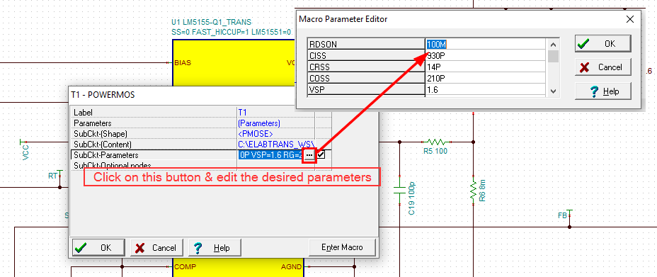
I'm working with LM51551-Q1 transient startup model (downloaded from WEBENCH Spicerack) in TINA-TI, simulating boost scheme, similar to the EVM module. Are there any chances of LM51551-Q1 average PSpice model being released/uploaded anytime soon to run AC analysis?
If not, is it possible to estimate scheme's generated noise in any other way?
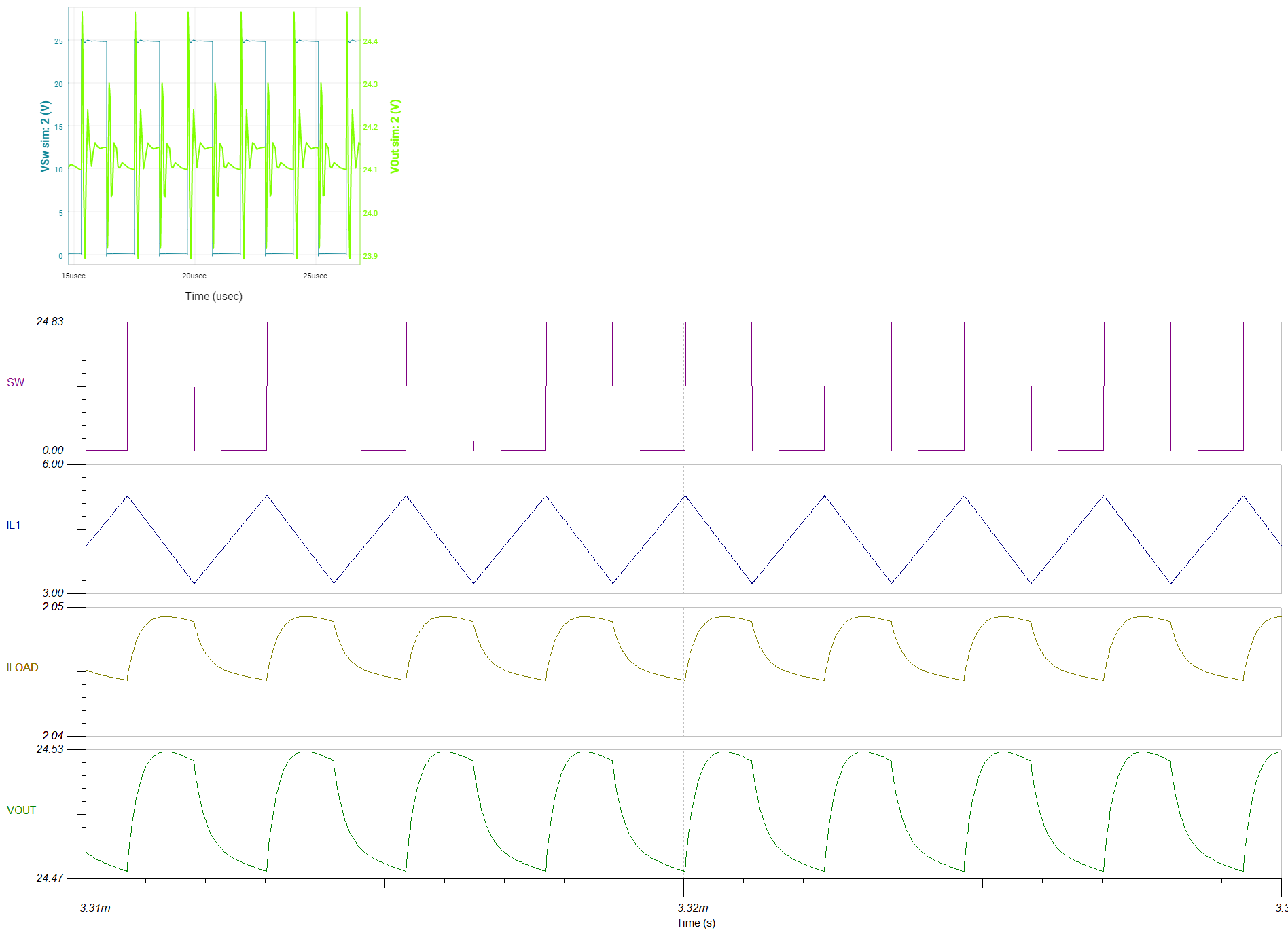
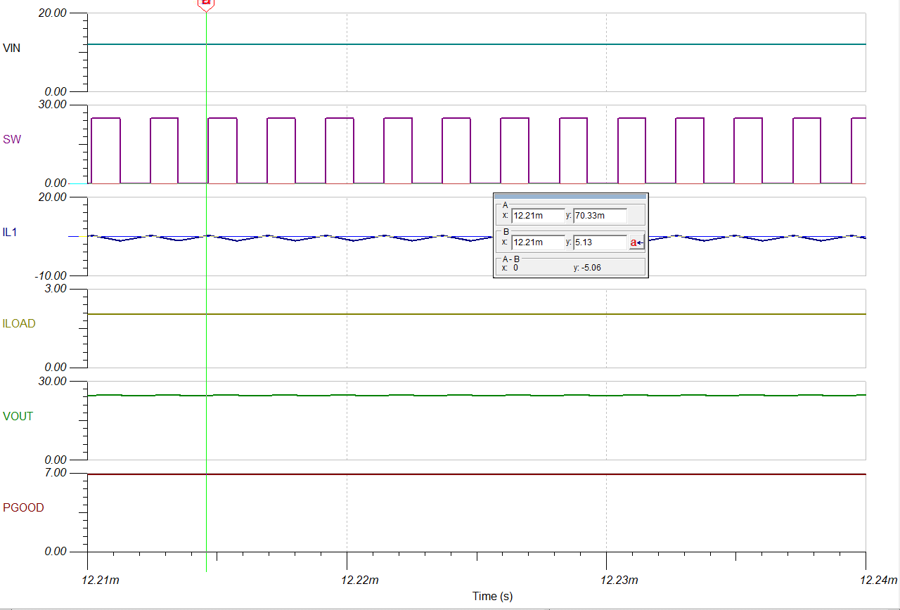
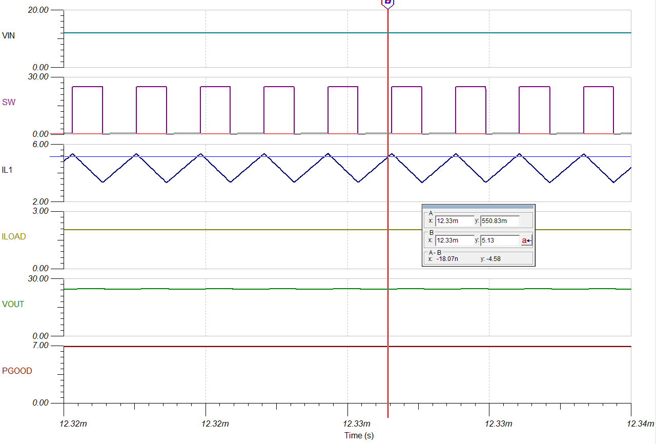
Also, I've done some steady state simulations with WEBENCH, where i got quite messy VOUT signals. On the other hand, results of VOUT in TINA-TI seems too good to me. Could it be that WEBENCH' elements have more parasitic "variables" evaluated in them? I'm attaching snips of sim's below.
Thanks in advance,
Justinas