This thread has been locked.

If you have a related question, please click the "Ask a related question" button in the top right corner. The newly created question will be automatically linked to this question.

BQ24092: Checking if connections are correct

Part Number: BQ24092

Hello,

I am making a device, which uses a 3.7V 750mA/h lipo battery. I want to have the battery power the device as normal and be able to be charged via micro USB when low. Also, if the battery is charging, the device can still operate, by receiving power via the micro USB. I believe the BQ24092 can do this.

I have read through the datasheet and designed everything on Altium and just wanted to check everything is correct before developing my device further (would rather not set my workshop of fire).

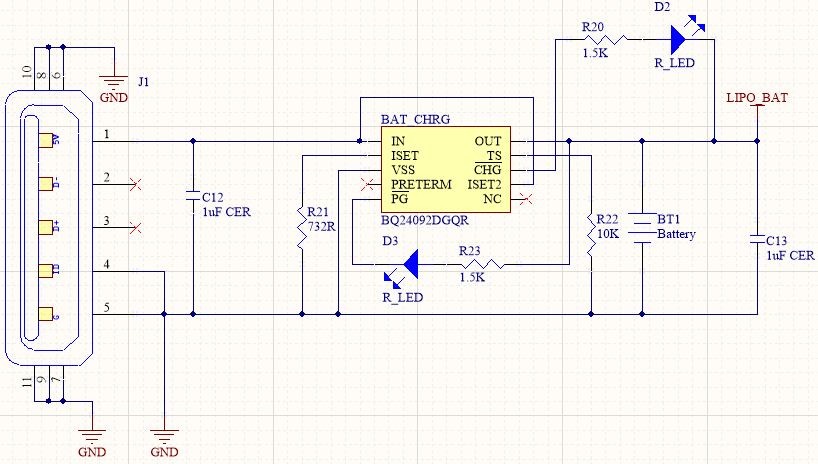
The connections are as followed:

  • Input is connected to the micro USB with a 1uF ceramic capacitor connected between IN and ground.
  • ISET is connected to ground with a 732R resistor based on the following calculations:
    • RISET = KISET/IOUT = 540/0.75 = 720 (732R resistor closest value I could find)
  • VSS is ground.
  • Pre-term in not connected (floating),which will set the termination to 10% and pre-charge 20%.
  • PG is connected via a LED and 1.5k resistor series to out.
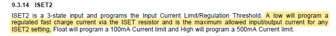
  • ISET2 connected to the input to make the charge current 500mA, when using USB.
  • CHG is connected via a LED and 1.5k resistor series to out.
  • TS is connected to ground, via a 10k resistor as the temperature feature is not used.
  • OUT is connected to the load, 3.7V 750ma/h lipo, PG and CHG pins. Also a 1uF capacitor to ground.

The circuit for this is below:


Some of the questions I have is:

  • Is the circuit correct for how I designed it to be?
  • If I did want to use the temperature pin, do I just connect the a 10k NTC thermistor (103AT) between the TS pin and ground?
  • Hello

    1.) If the Temperature Pin (TS) is not used 10k resistor to ground will keep unit in safe mode.  If used the NTC thermistor 103AT would be a good option.

    2.) circuit look OK some notes below:

    A.) PRETERM open --- yes will set at 10% but may want to add a resistor position if you have the room, would not install resistor.  This give you the option to adjust precharge or termination is need.

    B.) ISET2 to V-IN -- yes will set to 500mA input but charge current is set to 700mA, current will be limited. Couple of other things to consider.  Max voltage to ISET2 is 7V and V-in is 30V -- you are OK if overvoltage on input is not a concern. 

  • Thank you for the reply.

    I like the idea of having of the PRE-TERM pin, being able to be configured, as well as I will add the 103AT to the TS pin. With regards to what you mentioned about the ISET2 pin, is it that my charge current will be limited when charging the battery via the input and powering the load. As I have set it to 700mA, but ISET2 is set to 500mA (pulled high), this would only charge it at 500mA?

    Would it because in the datasheet it says:

    I think I have confused myself between the ISET and ISET2 pin. Should I set my ISET2 pin to ground? To have the charge current based on ISET.

  • Hi

    If you set ISET2 to Ground charge current can be greater than 500mA, set by ISET value.  If ISET2 is HI then max charge current is 500mA (input and output current).

    Most customers ground ISET2.