Because of the Thanksgiving holiday in the U.S., TI E2E™ design support forum responses may be delayed from November 25 through December 2. Thank you for your patience.

This thread has been locked.

If you have a related question, please click the "Ask a related question" button in the top right corner. The newly created question will be automatically linked to this question.

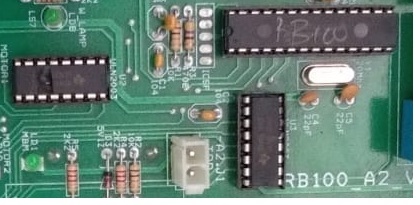
ULN2003A: IC BURNED

Part Number: ULN2003A

Hi all,

It is a failure issue in ULN2003A, ULN2003 has been used in similar design for nearly 12 years, but the 10% of failure happens in last two year.

These IC's are used to control a 24V DC battery operated Floor cleaning machine

The purpose of IC in our Floor cleaning Machine board as described below

1)      ULN2003AN (IC3)  - Here ULN2003AN is used to ON and OFF 2 Contactors and 5 Relays

2)      Another ULN2003AN (IC5) – Drive 2 number of relays.

       3)    74HC595 (IC2,4)  - Here 74HC595 is used to transfer the control signal from Microcontroller

        to ULN2003AN.

*Below figure shows the how ULN2003AN & 74HC595 IC used in schematic      


This is working very well. In some of the boards after 50hrs running the ULN2003 (either IC3 or IC5 or both) was failed.  In the failed condition the ULN2003AN outputs ON automatically (without control from microcontroller).

In some failure cases The IC2 and or IC4 also failed. We are exporting this product all over the world. This is the major failure in this product, and we are in crisis situation. Kindly suggest the exact failure cause for this issue and let us know the route cause. I listed out some of the failure conditions below,                                                                                                                                                 * IC got Externally Broken

                * IC burned                                                                                                       

                * IC Partially not working

                * IC Internally short

we measured the case temperature of the ULN2003A IC its also goes maximum up to 65 degree Celsius.

if case temperature is 65 means what is the junction temperature?

we measured the junction temperature according to TI datasheet for IC3

IC Pin no Load A V drop Power dissipated Thermal Resistance (from datasheet) Case Temp measured(Eg) Tc Junction Temp Estimated Tj
Pin16 BM cont 0.390 1.225 0.478      
Pin15 VM cont 0.220 1.040 0.229      
Pin14 Horn Rly 0.016 0.803 0.013      
Pin13 Lamp Rly 0.016 0.779 0.012      
Pin12 BM A1 Rly 0.086 0.840 0.072      
Pin11 BM A2 Rly 0.016 0.728 0.012      
Pin10 VM Rly 0.086 0.791 0.068      
0.884 54 65 112.72

Junction temperature - 112.72 degree Celsius is correct

  • Hello Kamalakannan,

    Welcome to E2E!

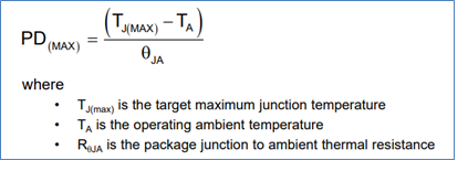
    The important thing to calculate here is the power dissipation across all of the channels, PD, and compare that to the maximum allowable power dissipation, PD(MAX). In the datasheet we have the following formula to calculate PD for an application:

    Next you have to calculate the worst case PD(MAX) for your application as specified in the datasheet:

    What is the ambient temperature (TA) that your device is operating at? In the datasheet we give specifications at a TA of 25ᵒC, however if your application is running in a higher/lower ambient temperature it is going to adversely affect the max power dissipation via the referenced formula.

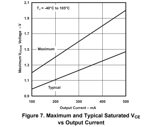
    Next- how are you calculating your voltage drop? Are you using Figure 1 or Figure 7 in the datasheet? These figures are the ones that you have to use for the appropriate voltage calculation as they will give you the worst case VOLi values and not the typical ones at a given time instance.

  • Hi Timothy logan,

    Thanks for your reply.

    i already calculated PD =0.884.

    PD(max) = (150-65)/67 = 1.2686.

    Power dissipation does not exceeds the maximum value.

    And i want to know what are the scenario to affects the ULN externally.

    Kindly suggest the exact solution for this case and tell the root cause.

  • Kamalakannan,

    The 884mW that you are calculating is based on the voltage drops of what you measured in the device, correct? This needs to be measured for the worst cast scenario in order to ensure proper device operation. Take the PIN16 you have listed on the table with a load current of 390mA, for example. Let's take a look at Figure 7 in the datasheet:

    The worst case VCE in this case will be approximately 1.8V. This would lead to a power dissipation of PIN16 to 702mW. For PIN15 this would lead to a  worst case VCE of approximately 1.45V and a power dissipation of 319mW. Accounting for these two differences alone we are looking at a power dissipation total of 1.20mW.

    Also- how are you measuring the case temperature of 65ᵒC? This is very close to the absolute max ambient temperature of 70ᵒC and any sort of measurement margins of error could be critical here as we are pushing the specifications listed in "Absolute Maximum Ratings".  Plugging in a value of 70ᵒC we get a PD(MAX) of 1.19W.

    The absolute maximum ratings are being pushed if not exceeded here. The best design decision would be to reduce the overall power dissipation of the part- specifically looking at your design I would recommend taking PIN16 and moving it to use a MOSFET. Alternatively you could also put a heat sink on the device (https://www.newark.com/c/cooling-thermal-management/heat-sinks) to help with the temperature getting too high. 

  • Hi Timothy Logan,

    u ask how are you measuring the case temperature of 65degree?

    i measured in outer case of the uln2003a at working time.and i have one doubt, if the case temperature & ambient temperature is same.

    in another case, Related to the previous project uln2003a get burned but the output load at maximum of 284mA.

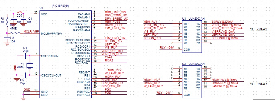
    i attached the schematic below,

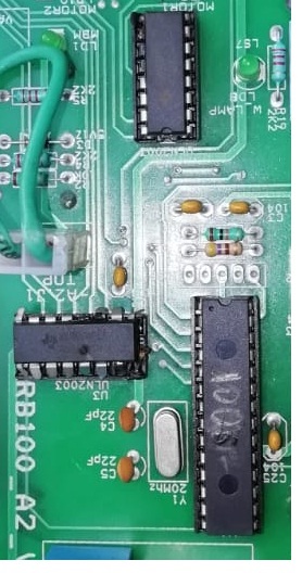
    i attached the burned images below,

    in this case power dissipation is 277mW.

    This circuit is working well in lab and In field some of the board get damaged after working minimum of 200 hours

    in which case uln2003a gets damaged like this,which is quite serious.

    Kindly suggest the exact solution for this case and tell the root cause.

  • Hello Kamalakannan,

    The issue here is instantaneous measured voltage drop versus the voltage drop that has been  tested and scrupulously characterized to be the most robust and worst case value to use during design. While the instantaneous measured voltage drop at any given sample time might be below the maximum specified in the datasheet, the maximum will vary due to environmental factors and general device behaviors.

    In this case going by Figure 7 in the datasheet and adding up the worst case scenarios for the data given it appears that the maximum values are being violated. While the device may seemingly operate while violating the absolute maximum specifications, it is not supported and long term reliability is not guaranteed.

    In this case the best solution would be to either add an external heat sink to help with the thermal performance or offload the higher current outputs to a device more suited for higher current devices such as a FET-based load switch. 

  • Hi Timothy Logan,

     I have one more doubt about free-wheeling voltage.
    In the ULN 2003 datasheet, the limit for free wheeling voltage is mentioned as 50V.
     To check this I measured the free-wheeling voltage of  a RELAY after it is just switched OFF. I disconnected  the COM pin of ULN from the vcc JUST FOR VOLTAGE measurement purpose.

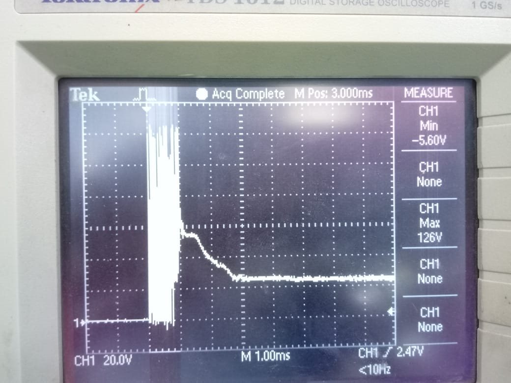
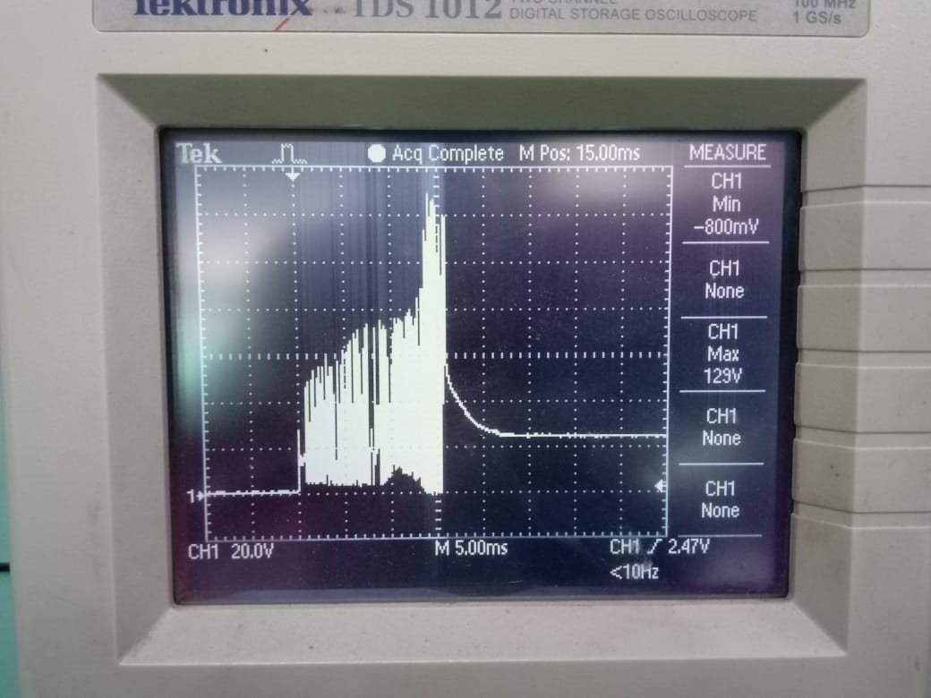
    Attached the waveform of the free-wheeling voltage. The voltage is 125V.

    GOODSKY RELAY WAVEFORM


    CONDUCTOR WAVEFORM

    Is the ULN internal clamp diode is capable to conduct 125V freewheelig voltage.?
    The relay we used is goodsky [RWH-SH-124D].

  • Hello Kamalakannan,

    Are you able to connect the COM pin to Vcc and retake these scope shots? It is not recommended to leave the COM pin floating since it may be pulled up during operation to above the abs max of the device (as you've shown :) ).

    Which spec in the datasheet are you referring to when you say "the limit for free wheeling voltage is mentioned as 50V"? The diode will clamp the voltage from output to COM, but the voltage will be clamped, and the voltage drop across the freewheeling diode will be much less than 50V.

    Thanks,

    Alek Kaknevicius

  • Hi alekkaknevicius,

             1.)We measured for this only for testing purpose. In design and production we tied COM pin to vcc.

    2.)I already asked in my earlier post that during our application the ULN case temperature measured is about 65deg C. Is this within limits. ? Else are you considering case tempetature and ambient temperature as same?


  • Hello Kamalakannan,

    With your case temperature at 65°C and your estimated power dissipation, the device is within spec. Is there any possibility that the device is exceeding any of the abs max ratings in the datasheet? This includes:

    • VOUT max = 50V
    • IMAX/channel = 500mA

    The 125V scope shots you captured would definitely stress the device past those limits, but I don't know if the device sees that during your normal application.

    Thanks,

    Alek Kaknevicius

  • Hi Alek Kaknevicius,

    The working voltage and current of the circuit,

    the operating voltage at max of 26V
    the current at each channel is
    PIin16 --- 400mA
    PIin15 --- 220mA
    PIin14 --- 16mA
    PIin13 --- 16mA
    PIin12 --- 86mA
    PIin11 --- 16mA
    PIin10 --- 86mA

    maximum temperature absorbed at case 65degree

    room temperature is 35degree.

    if case temperature & ambient temperature is same?

    kindly check above values are with in limits.

  • Hi Kamalakannan,

    In addition to having a high power dissipation, too much current is being driven through pin 16 on IC3.

    Figure 4 and Figure 5 show the relationship between the output current and numbers of channels being used. Using more channels of the ULN2003A at the same time will lower the amount of current that each channel can output. The amount of output current can further decrease if the ULN2003A is used at a higher duty cycle.

    In this case, regardless of the duty cycle, 390mA is already exceeding the amount of current you can output through the device. The device might be able to withstand this operation for a period of time, but the constant stress will affect the lifetime of the device.

    What is the duty cycle of your application?

    Best regards,

    Andy Robles