This thread has been locked.

If you have a related question, please click the "Ask a related question" button in the top right corner. The newly created question will be automatically linked to this question.

BQ25700A: Register configuration

Part Number: BQ25700A

Hello,

I am trying to do communication between Charger IC(BQ25700A) and STM32 controller by using I2C communication protocol.For taking the status of charging/discharging current of battery from charger ic,i have to configure registers in charger ic as shown below:

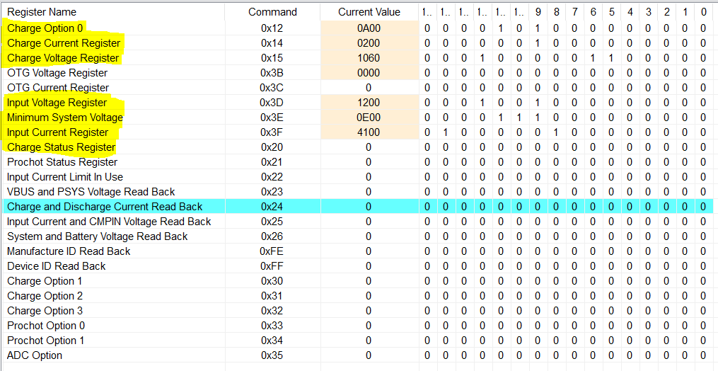
I have written C code according to given Read/write SMBus format in datasheet of charger ic but its not working. For loading current values in register address,i used array but i   am unable to understand read/write SMBus format as shown below.if someone have example related to this,please share it.


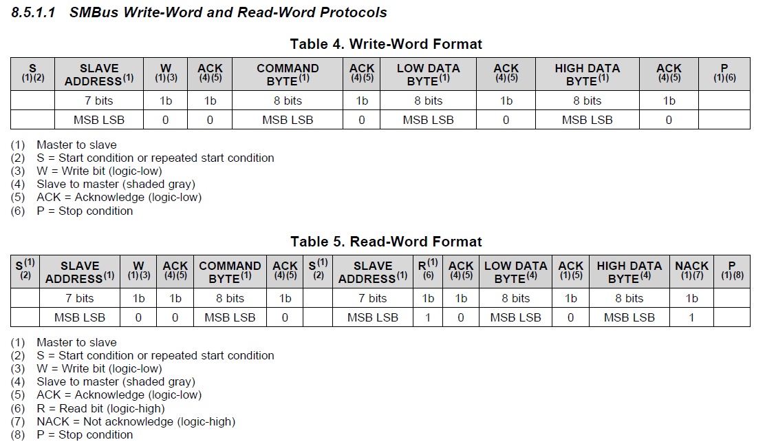
Datasheet of BQ25700A: http://www.ti.com/lit/ds/symlink/bq25700a.pdf

  • Hey Mohan,

    This may assist you since you are trying to use I2C to talk with an SMBus communication device:

    SMBus vs. I2C Communication - Charger Implementation.pdf

    You will also want to confirm how you are sending your data packets as well as the slave address to which you are writing.

    Regards,

    Joel H

  •  Thanks for your reply sir,your given information is very useful.As you said SMBus is a subset of of I2C communication protocol so instead of SMBus i written I2C communication protocol in my question means both the devices communicating through SMBus.I am sending data packets as per the SMBus Write-Word protocol and receiving the data as per the SMBus Read-Word protocol as you provided. SMBus slave device with address 0b00010010 (0x12H)

    I have attached my c code,Is it right way to configure registers of charger IC?

    /* USER CODE BEGIN Header */
    /**
      ******************************************************************************
      * @file           : main.c
      * @brief          : Main program body
      ******************************************************************************
      * @attention
      *
      * <h2><center>&copy; Copyright (c) 2020 STMicroelectronics.
      * All rights reserved.</center></h2>
      *
      * This software component is licensed by ST under BSD 3-Clause license,
      * the "License"; You may not use this file except in compliance with the
      * License. You may obtain a copy of the License at:
      *                        opensource.org/licenses/BSD-3-Clause
      *
      ******************************************************************************
      */
    /* USER CODE END Header */
    
    /* Includes ------------------------------------------------------------------*/
    #include "main.h"
    
    /* Private includes ----------------------------------------------------------*/
    /* USER CODE BEGIN Includes */
    
    /* USER CODE END Includes */
    
    /* Private typedef -----------------------------------------------------------*/
    /* USER CODE BEGIN PTD */
    
    /* USER CODE END PTD */
    
    /* Private define ------------------------------------------------------------*/
    /* USER CODE BEGIN PD */
    
    /* USER CODE END PD */
    
    /* Private macro -------------------------------------------------------------*/
    /* USER CODE BEGIN PM */
    
    /* USER CODE END PM */
    
    /* Private variables ---------------------------------------------------------*/
    I2C_HandleTypeDef hi2c1;
    
    UART_HandleTypeDef huart3;
    
    /* USER CODE BEGIN PV */
    
    /* USER CODE END PV */
    
    /* Private function prototypes -----------------------------------------------*/
    void SystemClock_Config(void);
    static void MX_GPIO_Init(void);
    static void MX_I2C1_Init(void);
    static void MX_USART3_UART_Init(void);
    /* USER CODE BEGIN PFP */
    
    /* USER CODE END PFP */
    
    /* Private user code ---------------------------------------------------------*/
    /* USER CODE BEGIN 0 */
    
    /* USER CODE END 0 */
    
    /**
      * @brief  The application entry point.
      * @retval int
      */
    int main(void)
    {
      /* USER CODE BEGIN 1 */
    int Buf1[4];
    int Buf2[4];
    int Buf3[4];
    int Buf4[4];
    int Buf5[4];
    int Buf6[4];
    int Buf7[7];
    uint8_t TxData;
    uint16_t RxData;
    
    int i;
    TxData=0x24;


      /* MCU Configuration--------------------------------------------------------*/
    
      /* Reset of all peripherals, Initializes the Flash interface and the Systick. */
      HAL_Init();
    
      /* USER CODE BEGIN Init */
    
      /* USER CODE END Init */
    
      /* Configure the system clock */
      SystemClock_Config();
    
      /* USER CODE BEGIN SysInit */
    
      /* USER CODE END SysInit */
    
      /* Initialize all configured peripherals */
      MX_GPIO_Init();
      MX_I2C1_Init();
      MX_USART3_UART_Init();
      /* USER CODE BEGIN 2 */
    
      /* USER CODE END 2 */
    
      /* Infinite loop */
      /* USER CODE BEGIN WHILE */
      for(i=0;i<5;i++)
      {
    
    	  //Register:Charge Option0//
    
    	  Buf1[0]=0x24; //slave address+write
    	  Buf1[1]=0x12;  //command byte
              Buf1[2]=0x00;  //LSB Data
    	  Buf1[3]=0x0A;  //MSB Data
    	  HAL_I2C_Master_Transmit(&hi2c1,0x12,Buf1,4,100);


    	  //Charge current register//
    
    	  Buf2[0]=0x24;
    	  Buf2[1]=0x14;
    	  Buf2[2]=0x00;
    	  Buf2[3]=0x02;
    	  HAL_I2C_Master_Transmit(&hi2c1,0x12,Buf2,4,100);
    
    	  //Charge voltage register//
    
    	          Buf3[0]=0x24;
    	  	  Buf3[1]=0x15;
    	  	  Buf3[2]=0x60;
    	  	  Buf3[3]=0x10;
    	  	  HAL_I2C_Master_Transmit(&hi2c1,0x12,Buf3,4,100);
    
    
    	  	  //Input voltage register//
    
    	  	                  Buf4[0]=0x24;
    	  		  	  Buf4[1]=0x3D;
    	  		  	  Buf4[2]=0x00;
    	  		  	  Buf4[3]=0x12;
    	  		  	  HAL_I2C_Master_Transmit(&hi2c1,0x12,Buf4,4,100);
    
    	  		  	  //minimum system voltage register//
    
    	  		  	                                  Buf5[0]=0x24;
    	  		  		  		  	  Buf5[1]=0x3E;
    	  		  		  		  	  Buf5[2]=0x00;
    	  		  		  		  	  Buf5[3]=0x0E;
    	  		  		  		  	  HAL_I2C_Master_Transmit(&hi2c1,0x12,Buf5,4,100);
    
    	  		  	//Input current register//
    
    	  		  		  		                                  Buf6[0]=0x24;
    	  		  		  			  		  	  Buf6[1]=0x3F;
    	  		  		  			  		  	  Buf6[2]=0x00;
    	  		  		  			  		  	  Buf6[3]=0x41;
    	  		  		  			  		  	  HAL_I2C_Master_Transmit(&hi2c1,0x12,Buf6,4,100);
    
    	  		  		//Read: charge/discharge current register  //
    
    	  		  		  			  		     Buf7[0]=0x24;
    	  		  		  			  	             Buf7[1]=0x24;
    	  		  		  			                     Buf7[2]=0x25;
    	  		  		  		                             Buf7[3]=0x00;
    	  		  		  		                             Buf7[4]=0x07;
    	  		  		  			  	         HAL_I2C_Master_Transmit(&hi2c1,0x12,Buf7,5,100);


    	  		  		  			  	         HAL_I2C_Master_Receive(&hi2c1,0x12,&RxData,1,100);
    
    
      }
      /* USER CODE END 3 */
    }
    
    /**
      * @brief System Clock Configuration
      * @retval None
      */
    void SystemClock_Config(void)
    {
      RCC_OscInitTypeDef RCC_OscInitStruct = {0};
      RCC_ClkInitTypeDef RCC_ClkInitStruct = {0};
      RCC_PeriphCLKInitTypeDef PeriphClkInit = {0};
    
      /** Initializes the CPU, AHB and APB busses clocks 
      */
      RCC_OscInitStruct.OscillatorType = RCC_OSCILLATORTYPE_MSI;
      RCC_OscInitStruct.MSIState = RCC_MSI_ON;
      RCC_OscInitStruct.MSICalibrationValue = 0;
      RCC_OscInitStruct.MSIClockRange = RCC_MSIRANGE_6;
      RCC_OscInitStruct.PLL.PLLState = RCC_PLL_NONE;
      if (HAL_RCC_OscConfig(&RCC_OscInitStruct) != HAL_OK)
      {
        Error_Handler();
      }
      /** Initializes the CPU, AHB and APB busses clocks 
      */
      RCC_ClkInitStruct.ClockType = RCC_CLOCKTYPE_HCLK|RCC_CLOCKTYPE_SYSCLK
                                  |RCC_CLOCKTYPE_PCLK1|RCC_CLOCKTYPE_PCLK2;
      RCC_ClkInitStruct.SYSCLKSource = RCC_SYSCLKSOURCE_MSI;
      RCC_ClkInitStruct.AHBCLKDivider = RCC_SYSCLK_DIV1;
      RCC_ClkInitStruct.APB1CLKDivider = RCC_HCLK_DIV1;
      RCC_ClkInitStruct.APB2CLKDivider = RCC_HCLK_DIV1;
    
      if (HAL_RCC_ClockConfig(&RCC_ClkInitStruct, FLASH_LATENCY_0) != HAL_OK)
      {
        Error_Handler();
      }
      PeriphClkInit.PeriphClockSelection = RCC_PERIPHCLK_USART3|RCC_PERIPHCLK_I2C1;
      PeriphClkInit.Usart3ClockSelection = RCC_USART3CLKSOURCE_PCLK1;
      PeriphClkInit.I2c1ClockSelection = RCC_I2C1CLKSOURCE_PCLK1;
      if (HAL_RCCEx_PeriphCLKConfig(&PeriphClkInit) != HAL_OK)
      {
        Error_Handler();
      }
      /** Configure the main internal regulator output voltage 
      */
      if (HAL_PWREx_ControlVoltageScaling(PWR_REGULATOR_VOLTAGE_SCALE1) != HAL_OK)
      {
        Error_Handler();
      }
    }
    
    /**
      * @brief I2C1 Initialization Function
      * @param None
      * @retval None
      */
    static void MX_I2C1_Init(void)
    {
    
      /* USER CODE BEGIN I2C1_Init 0 */
    
      /* USER CODE END I2C1_Init 0 */
    
      /* USER CODE BEGIN I2C1_Init 1 */
    
      /* USER CODE END I2C1_Init 1 */
      hi2c1.Instance = I2C1;
      hi2c1.Init.Timing = 0x00000E14;
      hi2c1.Init.OwnAddress1 = 0;
      hi2c1.Init.AddressingMode = I2C_ADDRESSINGMODE_7BIT;
      hi2c1.Init.DualAddressMode = I2C_DUALADDRESS_DISABLE;
      hi2c1.Init.OwnAddress2 = 0;
      hi2c1.Init.OwnAddress2Masks = I2C_OA2_NOMASK;
      hi2c1.Init.GeneralCallMode = I2C_GENERALCALL_DISABLE;
      hi2c1.Init.NoStretchMode = I2C_NOSTRETCH_DISABLE;
      if (HAL_I2C_Init(&hi2c1) != HAL_OK)
      {
        Error_Handler();
      }
      /** Configure Analogue filter 
      */
      if (HAL_I2CEx_ConfigAnalogFilter(&hi2c1, I2C_ANALOGFILTER_ENABLE) != HAL_OK)
      {
        Error_Handler();
      }
      /** Configure Digital filter 
      */
      if (HAL_I2CEx_ConfigDigitalFilter(&hi2c1, 0) != HAL_OK)
      {
        Error_Handler();
      }
      /* USER CODE BEGIN I2C1_Init 2 */
    
      /* USER CODE END I2C1_Init 2 */
    
    }
    
    /**
      * @brief USART3 Initialization Function
      * @param None
      * @retval None
      */
    static void MX_USART3_UART_Init(void)
    {
    
      /* USER CODE BEGIN USART3_Init 0 */
    
      /* USER CODE END USART3_Init 0 */
    
      /* USER CODE BEGIN USART3_Init 1 */
    
      /* USER CODE END USART3_Init 1 */
      huart3.Instance = USART3;
      huart3.Init.BaudRate = 115200;
      huart3.Init.WordLength = UART_WORDLENGTH_8B;
      huart3.Init.StopBits = UART_STOPBITS_1;
      huart3.Init.Parity = UART_PARITY_NONE;
      huart3.Init.Mode = UART_MODE_TX_RX;
      huart3.Init.HwFlowCtl = UART_HWCONTROL_NONE;
      huart3.Init.OverSampling = UART_OVERSAMPLING_16;
      huart3.Init.OneBitSampling = UART_ONE_BIT_SAMPLE_DISABLE;
      huart3.AdvancedInit.AdvFeatureInit = UART_ADVFEATURE_NO_INIT;
      if (HAL_UART_Init(&huart3) != HAL_OK)
      {
        Error_Handler();
      }
      /* USER CODE BEGIN USART3_Init 2 */
    
      /* USER CODE END USART3_Init 2 */
    
    }
    
    /**
      * @brief GPIO Initialization Function
      * @param None
      * @retval None
      */
    static void MX_GPIO_Init(void)
    {
    
      /* GPIO Ports Clock Enable */
      __HAL_RCC_GPIOB_CLK_ENABLE();
    
    }
    
    /* USER CODE BEGIN 4 */
    
    /* USER CODE END 4 */
    
    /**
      * @brief  This function is executed in case of error occurrence.
      * @retval None
      */
    void Error_Handler(void)
    {
      /* USER CODE BEGIN Error_Handler_Debug */
      /* User can add his own implementation to report the HAL error return state */
    
      /* USER CODE END Error_Handler_Debug */
    }
    
    #ifdef  USE_FULL_ASSERT
    /**
      * @brief  Reports the name of the source file and the source line number
      *         where the assert_param error has occurred.
      * @param  file: pointer to the source file name
      * @param  line: assert_param error line source number
      * @retval None
      */
    void assert_failed(char *file, uint32_t line)
    { 
      /* USER CODE BEGIN 6 */
      /* User can add his own implementation to report the file name and line number,
         tex: printf("Wrong parameters value: file %s on line %d\r\n", file, line) */
      /* USER CODE END 6 */
    }
    #endif /* USE_FULL_ASSERT */
    
    /************************ (C) COPYRIGHT STMicroelectronics *****END OF FILE****/
    

  • Hey Mohan,

    I only reviewed lines 116 to 167 and it seems correct. The data packet structure looks correct. 

    However, 

    For 168 to 176, make sure you are following the repeated start command for SMBus Read transaction. I'm not sure your current implementation does this.

    And make sure your device is looking for ACKs after almost every Word sent.

    Regards,

    Joel H

  •  Thanks for your reply sir,as you said 'make sure your device is looking for ACKs after almost every Word sent',how can i do that sir?

  • Hey Mohan,

    You I2C protocol implementation should already include an ACK to be compliant with the protocol specifications. If you follow the I2C spec, there is nothing else for you to do.

    Regards,

    Joel H

  •  Thanks for your reply sir,I know that the ACK is already included in I2C but my question is that how can i check that whether the sending the data from master to slave is correct or not?Means how can i know that master sending the right data and slave receiving the same data? For that we have to know the status of ACK bit,am i right sir?

  • Hey Mohan,

    First, I2C transactions will fail if there is no ACK signal. 

    Second, if you want to do a sanity check in your code, you can add a I2C read transaction after each write transaction to confirm that the data you sent over to a register address is the same thing that the charger reads out to you.

    You can check something, for example, like the ChargeOption0() register and confirm that disabling the watchdog timer actually occurred. 

    Regards,

    Joel H