This thread has been locked.

If you have a related question, please click the "Ask a related question" button in the top right corner. The newly created question will be automatically linked to this question.

BQ76930: Noisy Environment Compatible Design

Part Number: BQ76930
Other Parts Discussed in Thread: BQ78350-R1, BQ76PL536A

We are currently designing a BMS/Controller board for a low voltage battery pack. The board includes TI's bq76930 and bq78350-R1 for monitoring and fuel gauging purposes. 

The battery will be charged via alternator and the operating environment will be noisy. We have some worries about EMI/EMC and transient/surge susceptibility of the board.

As different from the typical application we added;

  • Strong TVS array on the PACK side of the board for transient and surges in order to protect the FETs and to keep the transients away from the cells, so the board
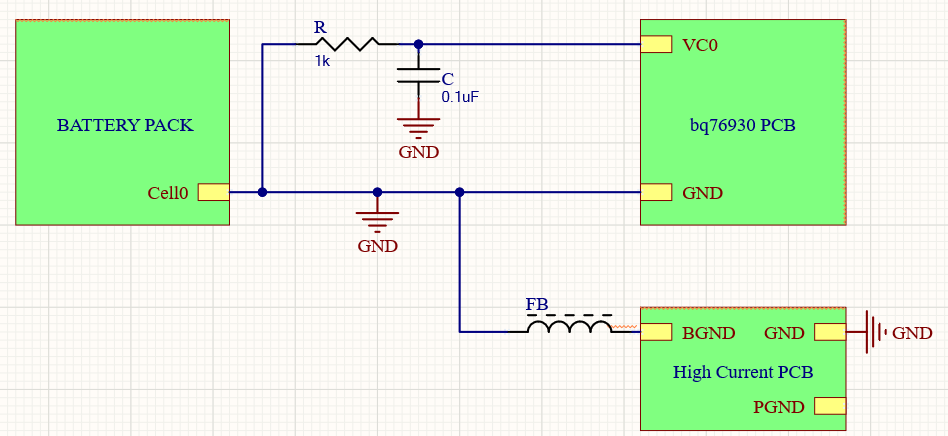
  • 600R (@100MHz) ferrite beads to the cell inputs

  1. I've seen that TI adds some low capacitance capacitors (~3300pF) to the cell inputs as an EMI filter (bq76PL536A). Would that be required for bq76930?
  2. Considering that the board have transient/surge filter on the PACK side do we still need a precaution on the cell inputs? 
  3. Does bq76930 require a zener diode on the cell inputs in order to clamp the voltage to the ICs limits for hot plug-in etc. conditions?
  4. Does the reference filter from the datasheet for current sensing inputs (SRP,SRN) enough the filter the noise in this environment?
  5. Should we make some changes on the I2C and SMBus lines (which are <12cm/5")? Like stong pull up?
  6. Would you have another suggestions on the optimization of the bq76930-bq78350-R1 circuitry?

Thank you,

  • Hi InProgress,

    1. Similar capacitors may be beneficial

    2. Cells can have an inductive response.  With the FETs on the filter will be connected, consider what happens when the FETs switch off.  SCD is often the highest transient.  The BQ76930 tends to limit switching speed to avoid large transients.

    3. It depends on your system design and connection technique.  The BQ76930 has no special protection on its inputs. See the application note "Top 10 Design Considerations" http://www.ti.com/lit/pdf/slua749  in the product folder.

    4. The sense filter is generally suitable.  See the application note for clamping the pins if needed.  Added capacitance will slow response of the current.

    5. Stronger pull up will improve rise times and should reduce noise susceptibility on the I2C lines. The EVM uses 10k pull ups for low current.

    6. Standard design practices for EMC should be helpful. Batteries tend to have long interconnects which act as antennas.  Use attenuation and shielding where needed.

  • An update;

    I'm planning to use a current shunt resistor (~100uR) which won't be mounted on the same PCB. I will carry the sense pins with a twisted-pair cable which I believe will be ~15-25cms long. The RC filter and differential capacitor on the SRN-SRP pins will remain close to the IC. Does TI have any recommendations or restrictions on this? 

  • Hi InProgress,,

    Sounds like a good approach.  Be aware of the voltage drops in the high current path and reference the IC appropriately to limit the voltage between the reference (VSS) and the inputs for VC0 and SRP.

  • The high current path of the BMS is a seperate PCB. So my plan is to connect an extra cable from the cell0 of the battery pack to bq76930 PCBs GND.

  • Hi InProcess,

    Filter as needed for the system.  Remember the signals into the BQ76930 are referenced to its VSS, on its PCB signals should be filtered with respect to VSS.