This thread has been locked.

If you have a related question, please click the "Ask a related question" button in the top right corner. The newly created question will be automatically linked to this question.

BQ76940: BA76940 Bring-up Tests

Part Number: BQ76940

Hi, 

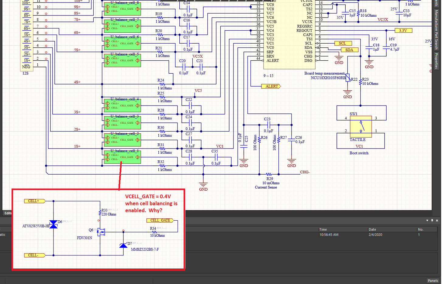
I'm getting boards back soon, can someone suggest the order to connect the battery cells and some test points that I should check to make sure the surrounding circuitry is OK and soldered properly.  Mostly I'm afraid of backwards diodes and things like that.  Is there a test point guide that I can use to bring-up the board?  Might make a good appnote.

Thanks,

Erik

  • Hi Erik,

    Connecting VSS first and then connecting each of the cells from the bottom up is the best and should be safe. You can measure the voltages at the VCx inputs as you connect the cells to make sure the correct voltage is seen be the device. Section 10 of this app note goes into more detail on cell connection considerations: http://www.ti.com/lit/an/slua749a/slua749a.pdf  After the cells are connected, the device will boot up with a rising voltage on the TS1 pin - at that point you should see the REGOUT pin voltage turn on. You should also check the voltages at VC5X, VC10X, CAP1, CAP2, CAP3, to make sure everything is as expected.

    Best regards,

    Matt

  • Thanks Matt, 

    Also, what are the minimum connections that must be done to start I2C communication?  Is it just that REGOUT needs a voltage?  I'm just thinking if I want to solder the bare minimum components first to start talking to the BQ76940 device.

    Erik

  • Hi Erik,

    REGOUT is an output and will turn on once the device has power and the BOOT pin has toggled. The cells should be connected and REGSRC, VC5X, and VC10X should all have power to ensure the device does not go into Shutdown mode.

    Best regards,

    Matt

  • Just wanted to verify that REGOUT will be 0V until I toggle that BOOT pin, is this correct?  I'm worried that my microcontroller will boot up and will detect I2C errors trying to read the BQ76940 if it is still in SHIP mode.  What sort of delay should I put in when the REGOUT power comes on before I start reading over I2C?  10ms ok?

    Is there any issue with backpowering REGOUT for programming my microcontroller before I build up the battery connections?  Or should I wait to program until after the battery pack is fully connected?

    Erik

  • Hi Erik,

    That is correct - 10ms should be okay according to the datasheet. I think it should be okay to back-power REGOUT, but it may be safest to disconnect from the BQ76940 if it is possible on your board. 

    Best regards,

    Matt

  • Hi Matt,

    I haven't tested everything yet, but so far the new board is working well and I am able to communicate and read voltages. So thanks for the help!

    Quick question, I was under the impression that the current could be monitored, but instead I only see a columb counter.  Is there any way to read the current in real time directly?  Or will I have to monitor the columb counter across a known amount of time and back-calculate?

    Thanks,

    Erik

  • Hi Erik,

    The coulomb counter is an integrating converter - it may be considered an average over the 250-ms integration period. To calculate current, divide the voltage reported by the coulomb counter by the sense resistor value:

    Current = CC value x CC LSB value / sense resistor

    Best regards,

    Matt

  • Got it, that makes sense, thank you!

    It seems I'm having an issue with I2C write.  My impression from the datasheet is that the bq7694006DBT does not use the CRC, so I don't need to send it.

    I'm attaching my I2C write and then readback transaction for your review.  As you can see the bq76940 is communicating without error, so I really don't understand why I can't seem to write to the part.  Is there any possible mode where the chip simply won't allow writes?

    The only other clue I have is that i'm only running at 63kHz I2C clock frequency, but I don't see how that would make much of a difference.

    Thanks for your help Matt!

    Erik

  • Ah, it was a fault.  Once I cleared it I can write just fine.

  • That's good to hear. Setting the Alert pin as an interrupt to the MCU is helpful to prompt the MCU to read the fault register and clear faults.

    Thanks,

    Matt

  • Hey Matt,

    All my cell balancing circuits seem to be working except the first cell.  Can you take a quick look at this schematic again?  The gate drive should be approximately equal to 2V (the cell voltage / 2), but I only see 0.4V.  It seems to me that the BQ76940 might be clamping, like maybe its damaged or something?  I checked to make sure the zener diode polarity is correct, and that R31 and R32 are actually 1k and R34 is 10k.  I've simulated the circuit in LTSpice with simple switches for the BQ76940 and it seems fine.

    Let me know what you think, thanks!

    Erik

  • Hi Erik,

    The schematic looks good, so I'm not sure why the voltage would be so low on the FET gate. It might be damage to the device.

    Regards,

    Matt

  • Hi Matt,

    Today I left the board alone, when I came home I noticed that SCL was pulled low, my microcontroller couldn't communicate with the part.  After disconnecting the battery pack and reconnecting, SCL was fine.  Do you know of any reason why the bq76940 would pull the SCL line low permanently?  I wish there was a reset pin so I could reset the controller.  I'm a bit worried now...

    UPDATE 1: It seems that the ALERT pin is high most of the time and clearing the status register doesn't clear the fault.  I guess this chip is damaged, I will try to replace it.

    Unfortunately I need to use a connector to keep applying the battery pack to the chip, so I can't guarantee which cells are coming up first.  I have lots of TVS / Zeners around the circuit for protection, but do you think the out of order sequencing can damage the chip?

    UPDATE 2: I replaced the bq76940 with a new one.  After building the pack up from cell 1 to cell 12, I again get the SCL low problem.  Then after yanking the connector out and then back in fixed the issue.  But I noticed that I didn't have a delay from power-up to I2C start.  So, I was trying to communicate with the BQ76940 before it was ready, but I wouldn't expect it to yank SCL down indefinitely, was just expecting a NACK.  In addition, I still see that cell 1 is not balancing properly due to a low gate drive (0.4V) for the external MOSFET.  So, I think these issue are looking more like a design problem then a damaged part problem.

    Erik

    Latest Schematic:

    1538.BMS12S.pdf

  • Hi Erik,

    Sorry to hear about the issues you're seeing. SCL should not be driven by the BQ76940 since it is a slave. Are you sure the MCU is not driving this low? Do you see any faults in the status register when the ALERT pin is driven high? You may also need to clear the fault condition that is causing the Alert pin to go high.

    I will go through the schematic and look for any potential issues. In the mean time, it might be good to review Section 10 of this app note if you haven't already about random cell connection: http://www.ti.com/lit/an/slua749a/slua749a.pdf

    Regards,

    Matt

  • Ok, I guess I was thinking its possible that the slave holds the SCL line low because some slaves do that for clock stretching.  I will see if I can isolate just the microcontrioller.  Yes, I can clear the fault in general after the ALERT pin goes high, but there have been a few cases I've seen where clearing the fault has no effect and the ALERT pin stays high.

    Thanks for the Random Cell documentation, I see this sentence: 

    If the VC0 input is not connected to battery-, it can be pulled to a high voltage. While no damage was observed at TI from this condition in limited testing, connecting the bottom of cell 1 input to VSS on the board at least during cell connection is recommended.


    So I suppose its possible that I'm damaging VC0.  The 0.4V voltage I'm seeing seems like it could be an internal body diode, like there is a resistive short internally to a higher voltage, so you get this sort of diode drop that is pull-ed up to another voltage.  But unfortuantely we don't have access to the VC0 pin directly to connect to Batt- during the connection process, I would need to update the schematic and use a jumper or something.

    EDIT 1: On second thought, if you connect VC0 input to the battery- the cell 1 will be discharging.  I'm not sure I understand this recommendation.

  • Hey Matt,

    I built up a new board and this time did NOT do random cell connection.  I've observed that cell 1 is now operating properly.  So I believe that random cell connection is not advised for my setup, as VC0 was damaged in both parts I tested.  I'm not sure if this is because I was using NMOS balance transistors (vs PMOS that TI normally uses) or what, but I have a path forward now.

    Thanks for your help, I think everything is sufficiently debugged now from a hardware standpoint and I am just tweaking firmware now.

    Erik