This thread has been locked.

If you have a related question, please click the "Ask a related question" button in the top right corner. The newly created question will be automatically linked to this question.

TPS22968-Q1: Reverse current configuration - leakage?

Part Number: TPS22968-Q1

Hi

I'm experiencing something I didn't expect using this switch. I'm using it in reverse current protection configuration. 

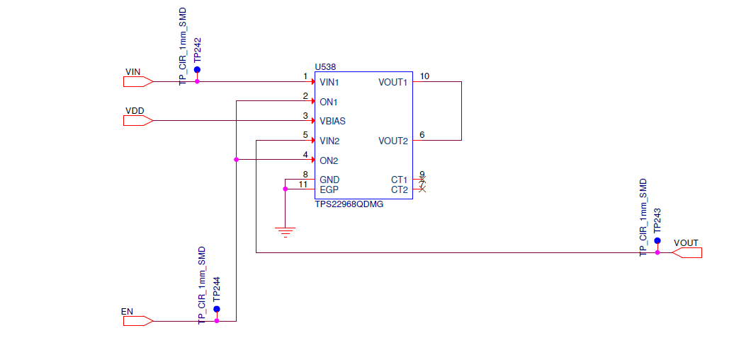
My EN signal is 3.3V and my bias voltage is 4.5V.

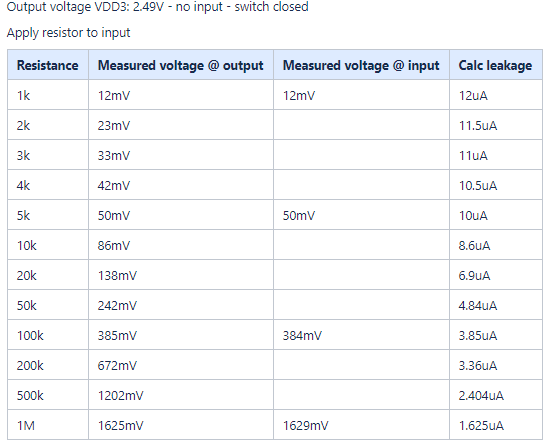
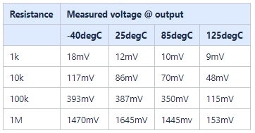
If I close the switch, but I don't have anything connected to the VIN (disconnected the power supply), I still measure close to 3V on the output???

This makes me a bit concerned for leakage of some kind.

Any ideas?

Best regards

Jon Eirik Sternang

  • Hello Jon,

    Quick question regarding your schematic- in the situation that you are seeing a leakage on the output is a load connected? If that load is connected does it have some under-voltage logic that would disconnect it in this case? The theory here is that a floating load would potentially cause leftover capacitance and account for that leakage that you are seeing. 

    Also in the situation where you see the leakage do you have the the supply turned on and then disconnect it while the ENABLE is high or is this state from a cold start up? A few scope shots of the test points you have on your schematic would be helpful to diagnose here: Enabling/Disabling the power switch both with the supply connected/disconnected.

  • Hi Timothy

    Thanks for the reply.

    During these measurements my load is not connected, only a voltage follower to monitor the voltage, and a multi-meter.

    To get an indication of the strength of the leakage, i measured the leakage voltage vs load resistance.

    As you can see I measure the same voltage on both input and output. The voltage is static even when using a load, so it's not simply a charge on a capacitance.

    We are using the device variant with discharge mechanism. Our power up sequence is always to apply VBIAS before we turn the switch on.

    Best regards

    Jon Eirik

  • I've tried to check this across temperature.

    Up to 85 degC, the leakage is 'fairly' constant, but at 125 degC it seems to drop significantly.

    I also tried to mount the variant without the discharge, but still see the same issue.

  • Jon,

    Apologies for the late reply here. I am going to try to reproduce this on a http://www.ti.com/tool/TPS22968EVM-007 in the lab here locally. Do you have any comment on what the loading conditions are? I realize this problem occurs when the load is floating, however for my testing this would help. 

  • Hi Timothy.

    Thank you for looking into this.

    In this case the load is high impedance (voltage follower and multimeter configured to measure voltage). From what I have seen the it doesn't matter if I put the resistors on the input or the output of the switch, there seems to be some leakage going through the resistors anyways.

    This is how I tested:

    1. No source connected to Vin

    2. Set switch on with no load

    3. Measure voltage on vout (might be in the range of approx 2.5V)

    4. Apply resistance on Vin or Vout

    5. Measure voltage

    6. Vary resistance and measure voltage again.

    Notice that we are using the reverse current protection configuration. I also tried to replace the part with the variant without discharge, but it gave similar results.

    Best regards

    Jon Eirik

  • Hi Jon,

    If my understanding is correct, then you are testing the device with only an output voltage on the device and the ON pins pulled low. Then you measure the input to see if there is any voltage present.

    One additional question I have on your setup - Do you have any voltage tied to the bias pin? The QOD circuitry gets its power form the VBIAS pin, so if it is un-powered then the device will not be able to activate the QOD. Can you run your test again with the VBIAS pin powered and see if it solves your issue?

    Thanks,

    Alek Kaknevicius

  • Hi Alek

    No, this is not the case.

    As I mentioned in the first post the EN is tied high, the VBIAS is connected to 4.5V and there's no driving source on either the input or the output.

    Still I measure voltage at both the input and the output. However this voltage is not capable of driving much current, but some.

    Best regards

    Jon Eirik

  • Hi Jon,

    Thanks for the clarification.

    With VBIAS high and ON high, both channels are on and QOD is active. With all the channels on, it makes sense that VIN and VOUT read the same voltage value since they are connected to each other. Without QOD on (ON has to be tied low) there is no discharge for this leakage from the device.

    One other thing to note is that even though the device is configured for reverse current blocking, it will not perform this function unless the ON pin is pulled low. When pulled high, the device will pass through current in both directions.

    Can you help me understand what your overall concern is with the device performing as you have measured it? Looking back at your original post, with the ON pin tied high, it would be expected to see leakage to VIN if it is left floating because QOD is not active and the device is on.

    Thanks,

    Alek Kaknevicius

  • Hi Alek

    Do you know where the leakage comes from?

    My concern is two-fold.

    Background: this device is being used on a test platform which is used for both manual testing and automated characterization of our devices

    1. The leakage may affect our current measurements

    2. The leakage may apply a voltage to our devices which is higher than they can handle (when operated manually)

    Can you refer to a section in the datasheet where the leakage is described?

    Best regards

    Jon Eirik

  • Hi Jon,

    We don't have a spec for this leakage because the conditions you mention are outside of our recommended operating conditions. Our minimum recommended VIN voltage is 0.6V, and by leaving the input/output voltages floating, the device is not being operated in the conditions under the datasheet electrical table. The leakage present here would be coming from the VBIAS pin, but we haven't characterized the case where VBIAS is present, ON is high, and VIN is not applied.

    The one spec that would help to understand the max possible leakage of the device would be the quiescent current from VBIAS since that would be the source of the leakage present on the input/output. The leakage to input/output would get worse with hotter temperatures, so if you are looking to see the max expected leakage from the device, that would be the way to do it.

    Thanks,

    Alek Kaknevicius