This thread has been locked.

If you have a related question, please click the "Ask a related question" button in the top right corner. The newly created question will be automatically linked to this question.

TPS548A20: Vo & Feedback connections w.r.t stability measurement perspective

Part Number: TPS548A20

Hi,

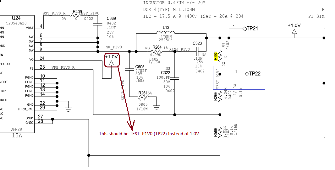
For the ease of doing stability analysis we have connected a 0 Ohms resister between Output voltage and Feedback resisters. During stability analysis we will replace 0 Ohms resister with injection resister and do the measurements.

But in regulators where Vout sense & Feedback pins both present, currently only Feedback will be isolated using 0 Ohms resister, Vout is not isolated.

As per my understanding for stability analysis whole feedback loop(including Output sense, feedback) should be isolated.

we are planning to route output sense voltage also from the other end of 0 Ohms resister.

Can you check whether our approach is OK. 

attached  an image to show the implementation.

  •  

    Because this circuit includes both an internal ramp generation circuit as part of the D-CAP3 control architecture, and an external RCC ramp generation circuit (R264, C323 and C322) merely changing the VO (Pin 24) connection is not going to change the loop injection point.

    In order to full split the loop with the external RCC network you will need to connect C323 and Pin 24 to the TP22 net, not just Pin 24.

    If you leave the connections as-is in the above schematic, the Loop Response will only show the voltage loop response and it will not include the inner loop adjustments to the ramp and On-time generator due to changes in VOUT.

  • Thanks peter,

    I am discussing this internally and will come back