This thread has been locked.

If you have a related question, please click the "Ask a related question" button in the top right corner. The newly created question will be automatically linked to this question.

UCC28780EVM-002: UCC28780 about Start-up problem

Part Number: UCC28780EVM-002
Other Parts Discussed in Thread: UCC28780

Hi sir:

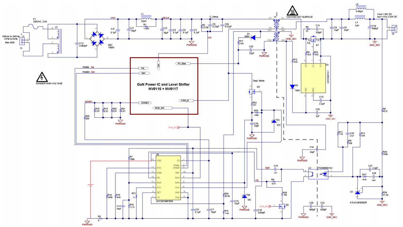
We have was remove auxiliary winding of the converter’s transformer Connect to VDD.

But 19.2V extra power supply to VDD.

Could help us why EVM  output voltage  is faill.

We have application input 9 V ,Could you recommend about start-up for low voltage.

Thinks

  • Hello Gene,

    Thank you for your interest in the UCC28780 ACF controller.

    This evaluation module (EVM) is designed to operate from the AC line voltage range of 85Vac to 265Vac.  It is programmed to start up at about 67Vac.
    If you are providing only 9V at the input, it will not start regardless of external VDD supply or not.

    It is not possible to modify this EVM to operate at very low input voltages.  The transformer primary inductance and turns ratios, the MOSFET sizes and current sense resistors, clamp caps, and many other circuit parameters are all designed for high voltage input (> 85Vac) to deliver 45W of output power.  Too many things will have to change (with significant changes, not minor ones) in order to run at such a low voltage. 

    In addition, certain internal controller parameters are optimized for the 85-265Vac input range.  Operation will be severely de-optimized with a 9-V input. 
    The UCC28780 is probably not the best controller to consider for a 9-V input application.

    Regards,
    Ulrich

  • Hi Ulrich:

    I am sorry to have confused you.

    You're right.

    But evaluation module (EVM) test voltage AC line setting 75Vac.

    We had remove auxiliary winding of the converter’s transformer disconnect  to UCC28780 VDD,But UCC28780 VDD  extra power supply setting 19.2Vdc.

    The auxiliary winding of the converter’s transformer only connect  to Pri_Bias.

    About application input 9 V ,We will not use EVM modify so this is new product redesign.

    Use evaluation module (EVM) just clear something up for us.

  • Hello Gene,

    I'm sorry, you are right, I was confused by the 9V. 

    I see now that your schematic diagram has erased the connection between U5-15 (VDD of controller) and Pri_Bias for the Gan ICs.  I missed that detail before my previous reply.

    Please restore this connection.  The GaN MOSFET-ICs also need bias power during start-up, or the EVM will not switch. The way you have it now, the ACF controller receives 19.2V from an external source, but the Gan ICs do not receive any power.  These Gan ICs (on page 2 of the EVM schematic) have built-in drivers that require bias voltage in order to drive the MOSFET.  The controller sends them gate-drive signals (PWML and PWMH), but they cannot switch because their drivers have no power. 

    Pri-Bias cannot have voltage until the transformer is energized by the MOSFETs, and the MOSFETs can't drive the transformer if there is no Pri-Bias voltage.
    You can reconnect VDD to Pri_Bias and drive the whole network from the external 19.2V source.  This should allow the EVM to switch.

    Note: The EVM will switch, and attempt to start beginning with short test pulses as described in the datasheet section 7.4.8 and Figure 30 (page 28).  If the AC input is still below the start-up threshold (75Vac) then the test will fail.  This start-up voltage test is described in the Brown-In section 7.4.10.1 (page  30) and it is the "Brown-in detection" item in the System Fault Protection Table 2.  If AC input is too low, it will fail the test and the controller will go in to a VDD-UVLO reset mode.  However, UVLO reset mode relies on VDD falling down to ~10V to restart the IC.  With external 19.2V on VDD, this cannot happen, and the IC will appear to hang up and never switch again. 

    You will need to manually lower the external source down below 10V, increase the AC input, then raise VDD back up above 17.5V to begin a new set of test pulses.  The UCC28780 controller does this all automatically with current through the SWS input from the switched-node sensing transistor Q2.  An external source for VDD defeats the UVLO-cycle auto-restart function. It is difficult to test the EVM with low AC input and external VDD because it does not cycle as expected.  You must cycle VDD down and up manually to mimic this.

    Regards,
    Ulrich

  • Hi Ulrich:

    Just as you have said

    IF I will to manually lower the external source down below 10V, That is external source VDD is faill.
    IF I will to manually upper the external source up over 19.2V, The IC will appear to hang up and never switch again.

    But i still have some questions.

    How disable function by the Brown-In or If it is possible, could you provide interior detail circuits help us solve this problem.

    Regards

  • Hello Gene,

    It is not possible to disable the Brown-in function.  This is the way the IC is designed to operate.  It is intended to be powered from a bulk voltage rail from the rectified AC line.  The VDD is charged up to the start-up threshold (~17.5V) through an internal path from the SWS input.  The SWS input is fed by a depletion -mode MOSFET connected to the bulk voltage.  If the bulk voltage is not high enough (based on the value of the upper VS input resistor divider), then the initial test pulses will fail and VDD will be allowed to discharge down to 10V and the cycle will start over.  It will automatically repeat this until the AC input voltage rises high enough to raise the bulk voltage high enough to generate the correct auxiliary voltage to generate the VS input current to reach the start-up threshold of 365uA and continue switching.  All of this is described in the datasheet.

    If you manually override this automatic cycling, then you need to thoroughly understand how the controller and the EVM work first without modification in order to be able to alter the design and still satisfy the controller's sequential state changes.  In any case, this controller is not like the simple PWM chips that start switching as soon as their VDD or VCC is high enough, regardless of all other inputs.  The UCC28780 has numerous protection features that specifically prevent switching if the external conditions are not within their design targets.  This includes adequate input voltage.  The EVM is designed to operate from 85Vac to 265Vac.  It would need extremely extensive changes, not a few simple ones, in order to operate from a very low input voltage... in addition to the manual VDD source operation. 

    I suggest to use the EVM as designed to study the normal power up and operation, and relate it back to the datasheet descriptions of each functional state.  Then, do a paper design for a 9-V input following the design procedure and determine what changes will be necessary.  Then decide if the result is feasible, or if the UCC28780 may not be the correct controller for your application.       

    Regards,
    Ulrich