Dear Team,
I am using LP55231 for turning on and off LEDs.I observed that it is turning on RED Led only not the other two.
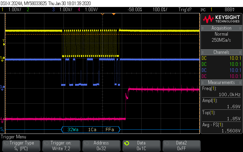
For RED LED it is toggling properly.Please find the attached Scope Image .For Blue and Green it is not at all toggling.
I am getting Vout(PIN NO=22) always zero.What is the expected value at Vout
Also please see the I2C Script I used
Please find my attached Schematic.
Regards
Hari
<aardvark>
<configure i2c="1" spi="1" gpio="0" tpower="1" pullups="0"/>
<i2c_bitrate khz="100"/>

<!--i2c_write addr="0x32" count="2" radix="16" nostop="0">00 40</i2c_write-->			//Example to comments any line if required

// ## LP55231 RGB LED Test Program by Ashvin D.##

//Circular 4-Mic Array S1813078_RED_STRIPE_005_A LEDs connections:
//DS1, DS2, DS3 LEDs Connections:
	//0x32	D7_DS1R, 	D1_DS1G, 	D2_DS1B
	//0x32	D8_DS2R, 	D3_DS2G, 	D4_DS2B
	//0x32	D9_DS3R, 	D5_DS3G, 	D6_DS3B

//DS4, DS5, DS6 LEDs Connections:
	//0x33	D7_DS4R, 	D1_DS4G, 	D2_DS4B
	//0x33	D8_DS5R, 	D3_DS5G, 	D4_DS5B
	//0x33	D9_DS6R, 	D5_DS6G, 	D6_DS6B

//DS7, DS8, DS9 LEDs Connections:
	//0x34	D7_DS7R, 	D1_DS7G, 	D2_DS7B
	//0x34	D8_DS8R, 	D3_DS8G, 	D4_DS8B
	//0x34	D9_DS9R, 	D5_DS9G, 	D6_DS9B

//DS10 LEDs Connections:
	//0x35	D7_DS10R, 	D1_DS10G, 	D2_DS10B


// register stuff
	// REG_CNTRL1 = 0x00;
	// REG_CNTRL2 = 0x01;
	// REG_RATIO_MSB = 0x02;
	// REG_RATIO_LSB = 0x03;
	// REG_OUTPUT_ONOFF_MSB = 0x04;
	// REG_OUTPUT_ONOFF_LSB = 0x05;

// Direct PWM control registers
	// REG_D1_PWM  = 0x16;
	// REG_D2_PWM  = 0x17;
	// REG_D3_PWM  = 0x18;
	// REG_D4_PWM  = 0x19;
	// REG_D5_PWM  = 0x1a;
	// REG_D6_PWM  = 0x1b;
	// REG_D7_PWM  = 0x1c;
	// REG_D8_PWM  = 0x1d;
	// REG_D9_PWM  = 0x1e;


// register stuff:
<i2c_write addr="0x32" count="2" radix="16" nostop="0">00 40</i2c_write>	//REG_CNTRL1 (0x00 = 0x40)
<i2c_write addr="0x32" count="2" radix="16" nostop="0">01 00</i2c_write>	//REG_CNTRL2 (0x01 = 0x00)
<i2c_write addr="0x32" count="2" radix="16" nostop="0">02 00</i2c_write>	//REG_RATIO_MSB (0x02 = 0x00)
<i2c_write addr="0x32" count="2" radix="16" nostop="0">03 00</i2c_write>	//REG_RATIO_LSB (0x03 = 0x00)
<i2c_write addr="0x32" count="2" radix="16" nostop="0">04 01</i2c_write>	//REG_OUTPUT_ONOFF_MSB (0x04 = 0x01)
<i2c_write addr="0x32" count="2" radix="16" nostop="0">05 FF</i2c_write>	//REG_OUTPUT_ONOFF_LSB (0x05 = 0xFF)

<i2c_write addr="0x33" count="2" radix="16" nostop="0">00 40</i2c_write>	//REG_CNTRL1 (0x00 = 0x40)
<i2c_write addr="0x33" count="2" radix="16" nostop="0">01 00</i2c_write>	//REG_CNTRL2 (0x01 = 0x00)
<i2c_write addr="0x33" count="2" radix="16" nostop="0">02 00</i2c_write>	//REG_RATIO_MSB (0x02 = 0x00)
<i2c_write addr="0x33" count="2" radix="16" nostop="0">03 00</i2c_write>	//REG_RATIO_LSB (0x03 = 0x00)
<i2c_write addr="0x33" count="2" radix="16" nostop="0">04 01</i2c_write>	//REG_OUTPUT_ONOFF_MSB (0x04 = 0x01)
<i2c_write addr="0x33" count="2" radix="16" nostop="0">05 FF</i2c_write>	//REG_OUTPUT_ONOFF_LSB (0x05 = 0xFF)

<i2c_write addr="0x34" count="2" radix="16" nostop="0">00 40</i2c_write>	//REG_CNTRL1 (0x00 = 0x40)
<i2c_write addr="0x34" count="2" radix="16" nostop="0">01 00</i2c_write>	//REG_CNTRL2 (0x01 = 0x00)
<i2c_write addr="0x34" count="2" radix="16" nostop="0">02 00</i2c_write>	//REG_RATIO_MSB (0x02 = 0x00)
<i2c_write addr="0x34" count="2" radix="16" nostop="0">03 00</i2c_write>	//REG_RATIO_LSB (0x03 = 0x00)
<i2c_write addr="0x34" count="2" radix="16" nostop="0">04 01</i2c_write>	//REG_OUTPUT_ONOFF_MSB (0x04 = 0x01)
<i2c_write addr="0x34" count="2" radix="16" nostop="0">05 FF</i2c_write>	//REG_OUTPUT_ONOFF_LSB (0x05 = 0xFF)

<i2c_write addr="0x35" count="2" radix="16" nostop="0">00 40</i2c_write>	//REG_CNTRL1 (0x00 = 0x40)
<i2c_write addr="0x35" count="2" radix="16" nostop="0">01 00</i2c_write>	//REG_CNTRL2 (0x01 = 0x00)
<i2c_write addr="0x35" count="2" radix="16" nostop="0">02 00</i2c_write>	//REG_RATIO_MSB (0x02 = 0x00)
<i2c_write addr="0x35" count="2" radix="16" nostop="0">03 00</i2c_write>	//REG_RATIO_LSB (0x03 = 0x00)
<i2c_write addr="0x35" count="2" radix="16" nostop="0">04 01</i2c_write>	//REG_OUTPUT_ONOFF_MSB (0x04 = 0x01)
<i2c_write addr="0x35" count="2" radix="16" nostop="0">05 FF</i2c_write>	//REG_OUTPUT_ONOFF_LSB (0x05 = 0xFF)


// RED LED TEST FOR DS1, DS2, DS3, DS4, DS4, DS5, DS6, DS7, DS8, DS9, DS10
<i2c_write addr="0x32" count="2" radix="16" nostop="0">1C FF</i2c_write>	//REG_D7_PWM (0x1C = 0xFF), D7_DS1R-ON
<i2c_write addr="0x32" count="2" radix="16" nostop="0">1D FF</i2c_write>	//REG_D8_PWM (0x1D = 0xFF), D8_DS2R-ON
<i2c_write addr="0x32" count="2" radix="16" nostop="0">1E FF</i2c_write>	//REG_D9_PWM (0x1E = 0xFF), D9_DS3R-ON

<i2c_write addr="0x33" count="2" radix="16" nostop="0">1C FF</i2c_write>	//REG_D7_PWM (0x1C = 0xFF), D7_DS4R-ON
<i2c_write addr="0x33" count="2" radix="16" nostop="0">1D FF</i2c_write>	//REG_D8_PWM (0x1D = 0xFF), D8_DS5R-ON
<i2c_write addr="0x33" count="2" radix="16" nostop="0">1E FF</i2c_write>	//REG_D9_PWM (0x1E = 0xFF), D9_DS6R-ON

<i2c_write addr="0x34" count="2" radix="16" nostop="0">1C FF</i2c_write>	//REG_D7_PWM (0x1C = 0xFF), D7_DS7R-ON
<i2c_write addr="0x34" count="2" radix="16" nostop="0">1D FF</i2c_write>	//REG_D8_PWM (0x1D = 0xFF), D8_DS8R-ON
<i2c_write addr="0x34" count="2" radix="16" nostop="0">1E FF</i2c_write>	//REG_D9_PWM (0x1E = 0xFF), D9_DS9R-ON

<i2c_write addr="0x35" count="2" radix="16" nostop="0">1C FF</i2c_write>	//REG_D7_PWM (0x1C = 0xFF), D7_DS10R-ON

<sleep ms="2000"/>														//Delay 2000ms

<i2c_write addr="0x32" count="2" radix="16" nostop="0">1C 00</i2c_write>	//REG_D7_PWM (0x1C = 0x00), D7_DS1R-OFF
<i2c_write addr="0x32" count="2" radix="16" nostop="0">1D 00</i2c_write>	//REG_D8_PWM (0x1D = 0x00), D8_DS2R-OFF
<i2c_write addr="0x32" count="2" radix="16" nostop="0">1E 00</i2c_write>	//REG_D9_PWM (0x1E = 0x00), D9_DS3R-OFF

<i2c_write addr="0x33" count="2" radix="16" nostop="0">1C 00</i2c_write>	//REG_D7_PWM (0x1C = 0x00), D7_DS4R-OFF
<i2c_write addr="0x33" count="2" radix="16" nostop="0">1D 00</i2c_write>	//REG_D8_PWM (0x1D = 0x00), D8_DS5R-OFF
<i2c_write addr="0x33" count="2" radix="16" nostop="0">1E 00</i2c_write>	//REG_D9_PWM (0x1E = 0x00), D9_DS6R-OFF

<i2c_write addr="0x34" count="2" radix="16" nostop="0">1C 00</i2c_write>	//REG_D7_PWM (0x1C = 0x00), D7_DS7R-OFF
<i2c_write addr="0x34" count="2" radix="16" nostop="0">1D 00</i2c_write>	//REG_D8_PWM (0x1D = 0x00), D8_DS8R-OFF
<i2c_write addr="0x34" count="2" radix="16" nostop="0">1E 00</i2c_write>	//REG_D9_PWM (0x1E = 0x00), D9_DS9R-OFF

<i2c_write addr="0x35" count="2" radix="16" nostop="0">1C 00</i2c_write>	//REG_D7_PWM (0x1C = 0x00), D7_DS10R-OFF

<sleep ms="100"/>														//Delay 100ms


// GREEN LED TEST FOR DS1, DS2, DS3, DS4, DS4, DS5, DS6, DS7, DS8, DS9, DS10
<i2c_write addr="0x32" count="2" radix="16" nostop="0">16 FF</i2c_write>	//REG_D1_PWM (0x16 = 0xFF), D1_DS1G-ON
<i2c_write addr="0x32" count="2" radix="16" nostop="0">18 FF</i2c_write>	//REG_D3_PWM (0x18 = 0xFF), D3_DS2G-ON
<i2c_write addr="0x32" count="2" radix="16" nostop="0">1A FF</i2c_write>	//REG_D5_PWM (0x1A = 0xFF), D5_DS3G-ON

<i2c_write addr="0x33" count="2" radix="16" nostop="0">16 FF</i2c_write>	//REG_D1_PWM (0x16 = 0xFF), D1_DS4G-ON
<i2c_write addr="0x33" count="2" radix="16" nostop="0">18 FF</i2c_write>	//REG_D3_PWM (0x18 = 0xFF), D3_DS5G-ON
<i2c_write addr="0x33" count="2" radix="16" nostop="0">1A FF</i2c_write>	//REG_D5_PWM (0x1A = 0xFF), D5_DS6G-ON

<i2c_write addr="0x34" count="2" radix="16" nostop="0">16 FF</i2c_write>	//REG_D1_PWM (0x16 = 0xFF), D1_DS7G-ON
<i2c_write addr="0x34" count="2" radix="16" nostop="0">18 FF</i2c_write>	//REG_D3_PWM (0x18 = 0xFF), D3_DS8G-ON
<i2c_write addr="0x34" count="2" radix="16" nostop="0">1A FF</i2c_write>	//REG_D5_PWM (0x1A = 0xFF), D5_DS9G-ON

<i2c_write addr="0x35" count="2" radix="16" nostop="0">16 FF</i2c_write>	//REG_D1_PWM (0x16 = 0xFF), D1_DS10G-ON

<sleep ms="2000"/>														//Delay 2000ms

<i2c_write addr="0x32" count="2" radix="16" nostop="0">16 00</i2c_write>	//REG_D1_PWM (0x16 = 0x00), D1_DS1G-OFF
<i2c_write addr="0x32" count="2" radix="16" nostop="0">18 00</i2c_write>	//REG_D3_PWM (0x18 = 0x00), D3_DS2G-OFF
<i2c_write addr="0x32" count="2" radix="16" nostop="0">1A 00</i2c_write>	//REG_D5_PWM (0x1A = 0x00), D5_DS3G-OFF

<i2c_write addr="0x33" count="2" radix="16" nostop="0">16 00</i2c_write>	//REG_D1_PWM (0x16 = 0x00), D1_DS4G-OFF
<i2c_write addr="0x33" count="2" radix="16" nostop="0">18 00</i2c_write>	//REG_D3_PWM (0x18 = 0x00), D3_DS5G-OFF
<i2c_write addr="0x33" count="2" radix="16" nostop="0">1A 00</i2c_write>	//REG_D5_PWM (0x1A = 0x00), D5_DS6G-OFF

<i2c_write addr="0x34" count="2" radix="16" nostop="0">16 00</i2c_write>	//REG_D1_PWM (0x16 = 0x00), D1_DS7G-OFF
<i2c_write addr="0x34" count="2" radix="16" nostop="0">18 00</i2c_write>	//REG_D3_PWM (0x18 = 0x00), D3_DS8G-OFF
<i2c_write addr="0x34" count="2" radix="16" nostop="0">1A 00</i2c_write>	//REG_D5_PWM (0x1A = 0x00), D5_DS9G-OFF

<i2c_write addr="0x35" count="2" radix="16" nostop="0">16 00</i2c_write>	//REG_D1_PWM (0x16 = 0x00), D1_DS10G-OFF

<sleep ms="100"/>														//Delay 100ms

// BLUE LED TEST FOR DS1, DS2, DS3, DS4, DS4, DS5, DS6, DS7, DS8, DS9, DS10
<i2c_write addr="0x32" count="2" radix="16" nostop="0">17 FF</i2c_write>	//REG_D2_PWM (0x17 = 0xFF), D2_DS1B-ON
<i2c_write addr="0x32" count="2" radix="16" nostop="0">19 FF</i2c_write>	//REG_D4_PWM (0x19 = 0xFF), D4_DS2B-ON
<i2c_write addr="0x32" count="2" radix="16" nostop="0">1B FF</i2c_write>	//REG_D6_PWM (0x1B = 0xFF), D6_DS3B-ON

<i2c_write addr="0x33" count="2" radix="16" nostop="0">17 FF</i2c_write>	//REG_D2_PWM (0x17 = 0xFF), D2_DS4B-ON
<i2c_write addr="0x33" count="2" radix="16" nostop="0">19 FF</i2c_write>	//REG_D4_PWM (0x19 = 0xFF), D4_DS5B-ON
<i2c_write addr="0x33" count="2" radix="16" nostop="0">1B FF</i2c_write>	//REG_D6_PWM (0x1B = 0xFF), D6_DS6B-ON

<i2c_write addr="0x34" count="2" radix="16" nostop="0">17 FF</i2c_write>	//REG_D2_PWM (0x17 = 0xFF), D2_DS7B-ON
<i2c_write addr="0x34" count="2" radix="16" nostop="0">19 FF</i2c_write>	//REG_D4_PWM (0x19 = 0xFF), D4_DS8B-ON
<i2c_write addr="0x34" count="2" radix="16" nostop="0">1B FF</i2c_write>	//REG_D6_PWM (0x1B = 0xFF), D6_DS9B-ON

<i2c_write addr="0x35" count="2" radix="16" nostop="0">17 FF</i2c_write>	//REG_D2_PWM (0x17 = 0xFF), D2_DS10B-ON

<sleep ms="2000"/>														//Delay 2000ms

<i2c_write addr="0x32" count="2" radix="16" nostop="0">17 00</i2c_write>	//REG_D2_PWM (0x17 = 0x00), D2_DS1B-OFF
<i2c_write addr="0x32" count="2" radix="16" nostop="0">19 00</i2c_write>	//REG_D4_PWM (0x19 = 0x00), D4_DS2B-OFF
<i2c_write addr="0x32" count="2" radix="16" nostop="0">1B 00</i2c_write>	//REG_D6_PWM (0x1B = 0x00), D6_DS3B-OFF

<i2c_write addr="0x33" count="2" radix="16" nostop="0">17 00</i2c_write>	//REG_D2_PWM (0x17 = 0x00), D2_DS4B-OFF
<i2c_write addr="0x33" count="2" radix="16" nostop="0">19 00</i2c_write>	//REG_D4_PWM (0x19 = 0x00), D4_DS5B-OFF
<i2c_write addr="0x33" count="2" radix="16" nostop="0">1B 00</i2c_write>	//REG_D6_PWM (0x1B = 0x00), D6_DS6B-OFF

<i2c_write addr="0x34" count="2" radix="16" nostop="0">17 00</i2c_write>	//REG_D2_PWM (0x17 = 0x00), D2_DS7B-OFF
<i2c_write addr="0x34" count="2" radix="16" nostop="0">19 00</i2c_write>	//REG_D4_PWM (0x19 = 0x00), D4_DS8B-OFF
<i2c_write addr="0x34" count="2" radix="16" nostop="0">1B 00</i2c_write>	//REG_D6_PWM (0x1B = 0x00), D6_DS9B-OFF

<i2c_write addr="0x35" count="2" radix="16" nostop="0">17 00</i2c_write>	//REG_D2_PWM (0x17 = 0x00), D2_DS10B-OFF

<sleep ms="100"/>														//Delay 100ms


</aardvark>