This thread has been locked.

If you have a related question, please click the "Ask a related question" button in the top right corner. The newly created question will be automatically linked to this question.

BQ25883: Fast-Charge CC problem

Part Number: BQ25883
Other Parts Discussed in Thread: BQSTUDIO

Hello, I use the BQ25883 to charger 2 NCR18650GA battery Sanyo (2s configuration).

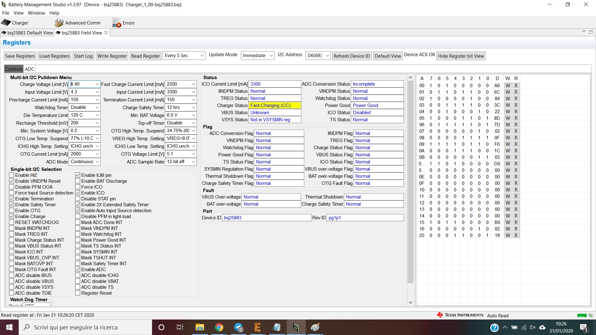
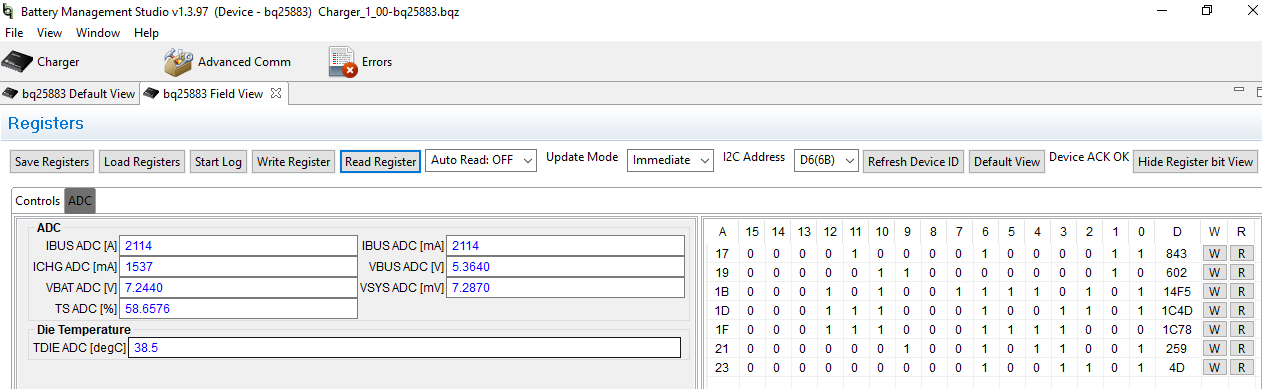
I use Battery Management Studio to know all register values and parameters.
I have connected a ammetter to measure charger current towards battery.

Trickle Charge and Pre-charge step run right.

But when Fast-Charge CC step start the ICHG ADC charger current on BqStudio is quite differet from what I read by my ammetter.

Furthermore, I see that in this step, current isn't costant as must been in Fast-Charge CC; it seems to be pulsed and it decrease slowly. Moreover, I have used a DC Power Supply that can provide up to 5A, but despite the ICO limit is setted at 3000 mA and Fast Charge Current Limit at 2000mA, the current never reached the set thresholds.

I have pull ILIM pin to ground with 383 ohm resistor to set about 3A input current limit.

Where is the problem?

Thank you!

  • Hi Fabio,

    What do the status flags report?  Is the charger entering thermal regulation?  Is VBUS_OVP or not power good ever reported?  Can you provide an oscope shot of VBUS, VBAT, IBUS, IBAT?

    Regards,

    Jeff

  • Hi Jeff,

    as you suggested me I have measured several parameters.

    Below pictures show voltage and current on battery and power supply.

    As you can see there is a proble with ICHG ADC measurements.

    I wait a response.

    Thank you for support.

  • Fabio,

    Is you ammeter in series between BAT pin and battery?  If so, can you remove it.  The ammeter adds resistance and also the autorange feature can cause issues.  After removing the ammeter, what are the results?

    Regards,
    Jeff

  • Hi Jeff,


    I have removed the ammeter but it doesn't change nothing.


    What can I try other?

    Thanks

    Fabio

  • Fabio,

    I tested an EVM and got the correct results, shown below, so it doesn't appear to be a BQStudio problem.  Does this happen on multiple boards/ICs or only 1?  If only 1, can you give me the top marking of the IC? 

    Regards,

    Jeff

  • Hi Jeff,

    Code on IC is (as you can see in npicture below):

    BQ25883
    TI 938
    AOXK

    I view your picture and I note you cannot to reach 2A of charge current, although setting is


    - ICO current limit 3300mA,
    - Input current limit 3300mA
    - Fast Charge Current Limit 2200mA.

    I expected that charger current can reach and go on 2000mA.

    Could it be some wrong setting?

    Thanks

    Fabio

  • Hi Fabio,

    As I recall, my input current limit was set to 2A so my charge current is power limited.  Even at IINDPM=ICO=3.3A, the IC is power limited at high battery voltage as shown in datasheet figures 1 and 2 page 13.

    I will investigate the history of this IC lot. 

    Regards,

    Jeff  

  • Hi Fabio,

    I tested another BQ25883 and it works as well.  Just to clarify, the IBAT ADC only reports current flowing from SYS to BAT (i.e. charging current) not current from BAT to SYS (discharge current for HiZ, supplement or OTG mode).  Your registers do not show that the charger is in any of those states, the IBAT ADC is not disabled so I would expect IBAT ADC channel to function.  Do you have another IC from a different lot that you can replace on the EVM board and test? 

    Regards,

    Jeff

  • Hi Jeff,

    When you say "...reports current flowing from SYS to BAT" do you mean from VBUS to VBAT?

    About IBAT ADC, sometime it reads right value. It isn't always zero.

    I have already try to replace the IC, but are all of the same lot.

    I have seen the figure 1 and 2, but I don't understand the maximum current charge and efficiency relationship. Cannot reach 2 A charge current?

    Thank you!

    Fabio

  • Hi Fabio,

    The IBAT ADC channel can only report current flowing from SYS output of the boost charger to the BAT pin.  It cannot report battery discharge current (so called negative current) flowing in the opposite direction such as when the charger is in OTG buck mode or in supplement mode (providing current to SYS load). 

    Regarding efficiency, all dc/dc converters have a maximum output power for their input power.  It is most easily estimated using an efficiency power balance where eff = Pout/Pin=(VSYS*ISYS+(VSYS-VBAT)*IBAT) / VBUS*IBUS.  The input power is either limited by the input power source, the charger's input current limit (IINDPM) or VINDPM or the charger's internal FET cycle-by-cycle current limit.   If you have no SYS  load, are in input current limit and the V(BAT)>MINSY, the equation simplifies to eff=VBAT*IBAT/VBUS*IINDPM.  Even at unreachable 100% eff for VBAT=8V, IINDPM=3.3A and VBUS=5V, IBAT = 2.06A.  When you add in losses (eff<100%), the maximum output current decreases. If you increase VBUS to 6V, you can almost reach 2A charge current.

    Regards,

    Jeff   

  • Hi Jeff,

    Do you have any news about lot number of BQ25883 that I have installed?

    Thanks.

    Fabio

  • Hi Fabio,

    Yes.  There were no anomalies with this lot. TI apparently sold or sampled all of this lot so I cannot check it.  If you want to ship me 1 or more units from the lot, I am happy to test them.  If so, I can friend you in this forum and give my shipping address privately.

    Regards,

    Jeff

  • Hi Jeff,

    Before I send you 1 sample of that lot I want to test the charge circuit with a BQ25883 of different lot.

    I'll send you the ic sample of first lot after this test.

    I'll keep you updated.

    Thanks.
    Fabio

  • Fabio,

    Thanks for you efforts!

    Regards,

    Jeff

  • Fabio,

    Any update on this?

    Regards,

    Jeff

  • Hi Jeff,
    I'm Federico, a colleague of Fabio, we are working together on this project.


    Today we tested a different production lot of BQ25883 and actually found a difference compared to the old one, on the same pcb design. The new BQ25883 performs almost well, although there is still something wrong


    I noticed that as soon as I connect a USB DCP with a maximum current of 2.1 A, this is recognized, but the current is not immediately fixed at 2.1 A, but the current oscillates in a range of 1.5 - 2 A for several seconds before stabilizing. At this juncture I have a strange behavior of the integrated circuit that gives off a stuning whistle. Sometimes stabilization occurs in just 2 seconds, other times a long time is required.

    Also I continue to have the problem on the ADC on the reading of the charge current, above a certain current threshold returns incorrect values, I would expect a value about 60% of the input current, but the returned value is a few tens of mA.


    What can these two problems be due to?
    Can it have anything to do with ICO optimization?


    I await a your response! Thank you!

  • Hi Jeff,

    I noticed that the problem of the oscillating current is solved if I send the command "Force ICO".

    Is it necessary to send that command every time to solve the problem?

    Thank you

    Federico

  • Frederico,

    Can I see oscope plots of the oscillation?  I assume the oscillation is VBUS, IBUS, ICHRG that is oscillating? I am assuming that ICO doesn't report complete until you Force ICO?  If you disable charge until ICO completes at power up, does the issue go away? 

    This device has a sensitivity to the output impedance of its input source and an aggressive VBUS OVP circuit.   In a worse case scenario, if the IBUS inrush current causes VBUS to droop to UVLO, which stops charging and then VBUS overshoots tripping the OVP circuit, the input may oscillate.  Adding more VBUS and/or PMID capacitance can help mitigate the input sources high output impedance.

    Regards,

    Jeff