This thread has been locked.

If you have a related question, please click the "Ask a related question" button in the top right corner. The newly created question will be automatically linked to this question.

TPS54494: Inrush current seen during the power up

Part Number: TPS54494

We are using TPS54494 on our design to generate four different rails 3.3V, 1.8V, 5V and 3.9V. In our design we are enabling all the buck by connecting it to 12V through a 10K pullup. The buck start turning on when the VIN raises to about 4.5V. At this instant we are seeing a combined inrush of about 2A. We have two 22uF capacitors on each rail and there are additional capacitance on the load side. 3.9V has largest of 220uF, 5V has 40uF. Rest have about 10uF.

Can you please let us know why are seeing inrush? Why is output inductor (4.7uH) not helping us here.

Let me know if you need any other details from our side. 

  • Hi, Raj 

    I think the inrush current is caused by charging all of output capacitors when 4 bucks worked at the same time when Vin is low(~4.5V). 

    Work around: 

    1. suggest to reduce the 220uF. 

    2. Suggest to enable all of bucks when Vin is rise up to 12V.  

  • Hi Zhao, 

    Thanks for your reply. 

    We cannot reduce the capacitance as it is recommended by the processor module.

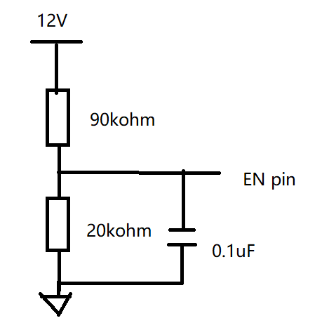
    We did try to delay the enable by adding a resistor divider but it doesn't work the intended way. Also the datasheet mentions ENx input resistance to be in range of 450K typ (220K min, 900K max). Is this resistor pull-down internally. It also doesn't follow the thresholds and the buck turns on when the EN pin is about 1V itself.

    Please look at the EN pin and let us know how can we implement the second point that you have mentioned

  • Hi, Sir 

    Yes, you are right, 450kohm is pull-down resistor. 

    suggest below configuration. 

  • We tried this but this doesn't work as intended. If you have a evaluation module, please try this out and see the problem yourself. We also increased the value to a very high resistor value but still it doesn't work. The buck turns on at about 1V much before the threshold of 2V.

    Can you please check with your design team and get back to us?

  • Hi, Sir 

    Maybe you can try to enlarge the cap from 0.1uF to 1uF. 

    I think the problem maybe at Vin slow rising up.  

    Could you show me your schematic? and waveforms for inrush current, Vin and SW1? And could you tell me where do you measure the inrush current? 

  • Increasing the cap to 1uF will further delay the rising time of the VEN pin voltage.

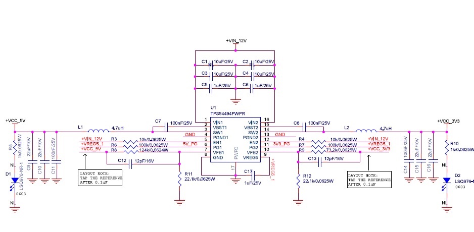
    Here is a snapshot of the schematics. I don't have the waveforms handy, will share on Monday. We are measuring the inrush at 12V input and see that after the charging of the input bulk capacitor, when the buck turns on there is a 1.5A-2A of inrush observed.


  • Hi, Sir 

    1. 1uF will delay turn on the bucks. 

    2. The schematic looks okay. 

    3. The buck converter has ~1ms soft start time. 

    Supposed 4 bucks work at the same time, according to Q=C*V. 

    For 3.9Vout, Q=(220uF+44uF)*3.9V=~1030uC. 

    For 5Vout, Q=(40uF+44uF)*5V=420uC. 

    For 3.3Vout, Q=(44uF+10uF)*3.3V=178uC. 

    For 1.8Vout, Q=(44uF+10uF)*1.8V=97uC. 

    charging curent(inrush current) = total Q/1mSec=~1.7A. 

    The calculated inrush current looks matched with your tested value. 

    Because the soft start time is fixed, so i think there is no good method to reduce inrush current, the only method is to reduce the output capacitance, or don't turn on 4 bucks at the same time.