Tool/software: WEBENCH® Design Tools
Hello TI,
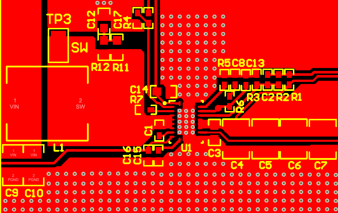
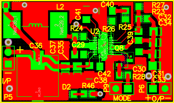
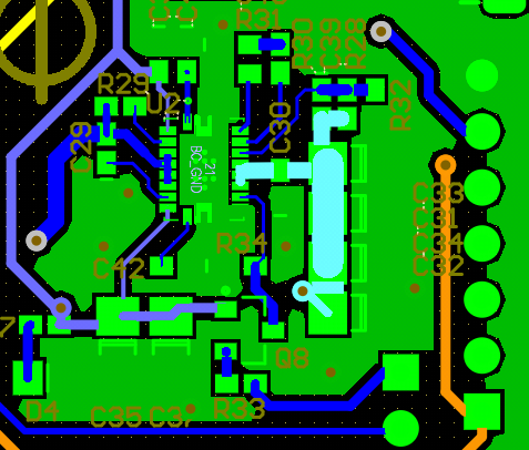
We Design system to drive Raspberry PI and other load(1.5A), using BQ24773 for battery charging and TPS61088 boost converter to provide required power to the load
Currently we are using only raspberry as load to system which I share schematic of boost converter and layout design
Because of odd value of Rfreq=R29 which 255Kohm as per the evaluation currently, we are using standard value which is 270Kohm but there is some noise(Humming Noise) when loaded the system that's why we try to adjust it by using 2 parallel resistor which is 1M || 330K ohms= 248KOhm, after the R29 replacement check all voltage's it's shows properly but when we Connect Load(Raspberry PI) to the system TPS61088 is short and dead ..?
Before that also we observe the damage's of TPS61088 because of overloading and insufficient input source when load was connected but it's over heat and damage permanently
What is the reasons of TPS61088 permanents damage..?
which protection available in the TPS61088, as per the datasheet the device provides 13.2-V output overvoltage protection, cycle-by-cycle overcurrent protection, and thermal shutdown protection if there is following protection available in the chip then why chip going to damage permanently..? and how to avoid this permanent damage of chip ..?
Any solid reason of R29 replacements can damage the TPS61088...?
We are operating TPS61088 in PWM mode by not mounting R33 & Q8 and R34=0ohm.
and R30 is used as 18Kohm instant of 17.4Kohm
I am attaching 2 different layout ver. files of tps61088 booster which have same issues and schematic of TPS61088 boost converter, schematic file is for B2 layout

There is also important things which want to mention here, we are designing consumer electronics products we require samples to test the new feature and existing system upgradation which your introduce new upgraded chip in the market, here is my humble request to unblock our domain which is phynart.com form TI sample which help us to design and develop thing fastly (It's my personal suggestion as a R&D engineer)
Now we don't have TPS61088 IC and we lose last IC today by testing.
Thanks and regards,
Rahul Surawase
rahul.s@phynart.com