Because of the holidays, TI E2E™ design support forum responses will be delayed from Dec. 25 through Jan. 2. Thank you for your patience.

This thread has been locked.

If you have a related question, please click the "Ask a related question" button in the top right corner. The newly created question will be automatically linked to this question.

BQ24773: Review schematic

Part Number: BQ24773
Other Parts Discussed in Thread: BQ28Z610,

Hello TI, 
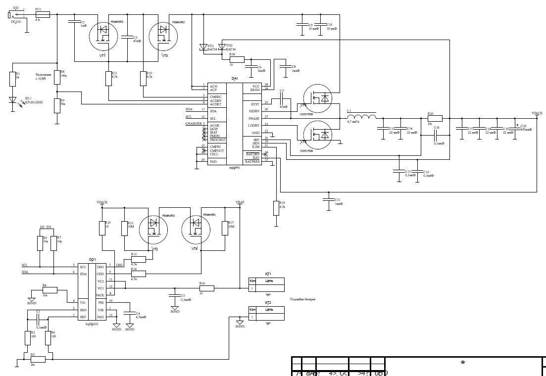
             I design charger and battery management system for Khadas 3 by using BQ24773 and bq28z610. It will be 12V/3A input, 1S/6A (20A*h) output charger.

And I try to use simpler schematic than that given in datasheet and EVM.

- I no need Input Current Monitor (ACN and ACP pins join together and connect to Vin).
- Also I reduce BAT current sensing resistor to 2mOhm.

- I no need BATFET cause I use outside MOSFET drived by MCU.


Will BQ24773 work correct in this schematic?

Thank you.

  • Hey Vlad,

    You cannot use this charger without the external PMOS BATFET populated. Because of the NVDC architecture, even if you do not want a separately regulated system voltage, the charger requires it to operate the linear mode correctly as well as disable charge correctly.

    I also worry that the regulation will be impacted by using a lower RSR resistor. 2mOhm may be too low for the converter to operate correctly. Consider using 5mOhm instead as minimum. 

    I would also caution against too much output capacitance. Without the capacitance and inductance you have, the resonant filter frequency is around 3.2kHz. On the contrary, according to the design, 10kHz is the minimum capacitance (see section 9.2.2.4 Output Capacitor of the datasheet).

    Regards,

    Joel H

  • Hi, Joel,

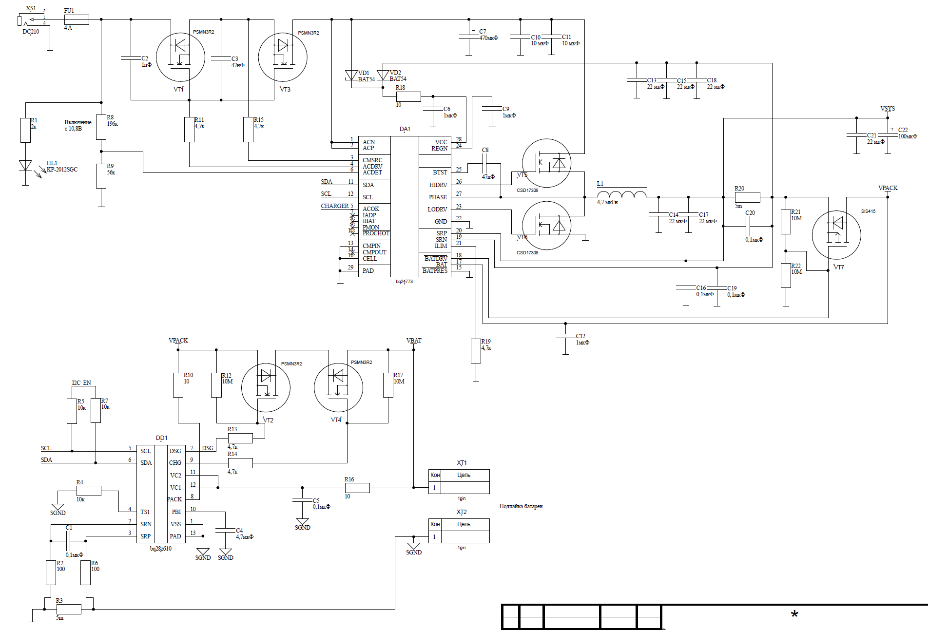
    I added PMOS BATFET to the circuit and change current sense resistor to 5mohm. As for the output capacitors, I made a quantity with a margin of a dc-bias effect.

    Is it correct now?

    Thank you.

  • Hey Vlad,

    Even considering the DC bias effect, the polarized capacitor you added with 100uF will largely NOT see the DC bias effect, unless it is also ceramic.

    I aluminum electrolytic, aluminum polymer, or tantalum polymer, I would consider reducing this to 68uF or 47uF to be on the safe size. Give DC bias, your ceramics capacitors @ 3x22uF x 20% derating at the worst case, you drop down to about 13uF. C13, C15, and C18 also an additional 66uF of capacitance, I would either remove these or reduce them significantly. For reference, the EVM only has 10uF at this node. 

    We also recommend adding 10-Ohm resistor between the BAT pin and the battery connection point. You can refer to the EVM schematic, component R23. 

    On your schematic, can you confirm the value of C12? Is the 0.1uF, or is it larger? If it is larger, please reduce to 0.1uF. 

    Keep in mind you have also pulled the ILIM pin to ground, without any resistor divider. This is fine but be aware the you will need to change the register settings to ignore this pin.

    We also recommend adding a 470pF capacitors across the LSFET gate-source, to help mitigate the effect of Cgd. 

    Regards,

    Joel H