This thread has been locked.

If you have a related question, please click the "Ask a related question" button in the top right corner. The newly created question will be automatically linked to this question.

TPS1H000-Q1: Current limit accuracy and capacitive load behaviour

Part Number: TPS1H000-Q1

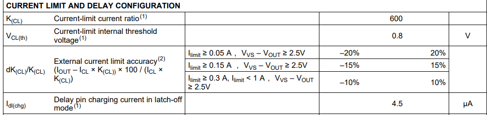
Good morning, I am using TPS1H000 to limit my output current to 200mA at 24V. I am not able to understand the expected accuracy when I set CL resistor to Rcl=2200ohm. By my calculation Iout limit is=218mA but how about accuracy: is it +/-20% max? Or it depends on output current rise time? Which are the maximum and minimum current limit in all the worst case? I would like to use component in auto retry mode because I don't have the possibility to drive In input.Then I have to optoisolate the fault signal ..

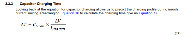
Another question is : Considering that I have on output a maximum load of 200mA and another load of 2mA but over an RC with 2uF and 150ohm--> How about the behaviour during the start-up? I think that I will overcome the maximum current due to 200mA and charging capacitor by 2mA, so Fault Pin will be low until capacitor is charged..Correct? How to avoid this behaviour? Is it possible to set a delay also in auto retry mode with a capacitor on delay pin?

 Thank you in advance, best reg

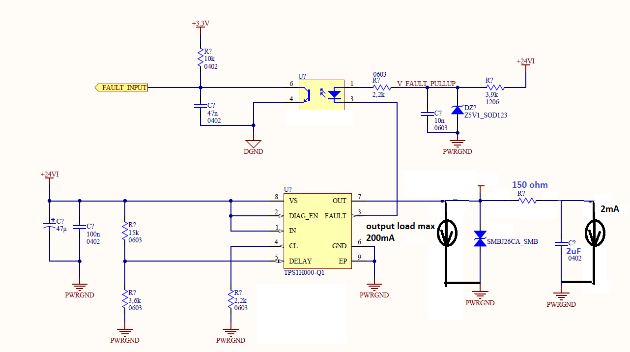
Attached my schematic.

  • Roger,

    The following parameters are going to be key from the datasheet:

    It's a little obfuscated, however the key here is in the comments- specifically the VVS - VOUT >= 2.5V. The 2.5V is the key number here. If you read the Adjustable Current Limit of Smart Power Switches application note it goes into detail about this in the 4.1 TPSxHxxx Current Limiting Accuracy during Current Creep section, however the current limit is generally used to protect against fast inrush events such as capacitor inrush and short-to-battery events. The current limit kicking in isn't so much about the time/duration of the event, however about the voltage drop from drain-to-source over the internal power-fet in the switch. This is where the 2.5V number comes into play.

    When the load is drawing more current the voltage drop over the internal power-fet (which looks like a resistor with a resistance of RON) is going to increase to the point where the FET goes out of the linear region and into the saturation region where the current limit kicks in. For a fast event like short-to-ground the drain-to-source voltage is going to exceed 2.5V almost instantaneously and the current limit will kick in right away. In a "current creep" scenariothe internal power-fet is going to hang out in the linear region which is where you get the 25% accuracy hit explained in the app note.

    As far as your second question about accounting for your inrush current during charging your capacitor the How To Drive Resistive, Inductive, Capacitive, and Lighting Loadapplication note is going to provide a lot of good information here. In your case your CLOAD is going to be a relatively low 2µF with a current limit of 200mA. Looking at the formula from the application note:

    This gives you a charging time of the capacitor of 240µS. Now let's look at the timing diagram from the datasheet for auto-retry mode:

    Looking at these timing parameters in the datasheet...

    The 2µF capacitor is going to fall within the "glitch" territory and not be a significant factor here for the current limit. One question I had was on the 150Ω resistor between loads. Is this meant to limit the current to the second load? In any case since the capacitance is so small this should not be a careabout with your set current limit.

    On a side note the DELAY pin should be pulled up with a 100kΩ resistor instead of a voltage divider as described in the 7.3.3 Standalone Operation section of the datasheet.

  • Good morning, thank you for the reply. I have some questions about it:

    1) After reading the app note, it seems that during inrush current where vvs-vout>2.5V the current limit accuracy is about +/-15% of the set current limit, whereas during low creep it is not predictable but a +/- 50% could be expected...

    2) I don't understand the formula of capacitor charging time in my case.. Considering 2uF capacitor discharged, after switching ON TPS1H000, I will have due load: the first is a current load of about 200mA (current generator drawn in black in the attached schematic) and the second of 2mA in parallel to 2uF. So the IINRUSH will not be 200mA in the formula...

    3)150ohm are for limiting current from ESD event on my load of 2mA (it simulates a logical components that draws 2mA and must be protected)

    4) If I use a resistor divider in the DELAY pin as in the schematic does not work? It is mandatory to use only a pull-up of 100kohm?Why?

    Thank you...

  • Hello Roger,

    1. This is correct- however keep in mind that the majority of scenarios are going to involve a sharp increase in dv/dt such as a capacitor charging or short-to-ground scenario. The current creep scenario mentioned is very niche. In your use case are you expecting a load step/current creep scenario where the load gradually decreases in resistance causing the current limit?
    2. I think I might be misunderstanding the intent here. You have a 2.2kΩ resistor connected to your CL pin. Doing the math in the datasheet this will yield you a current limit of 218mA. Is this the intent? In general your current limit should be comfortably above what your DC steady state continuous current will be. If in normal operation your current limit is 218mA you should set your current limit to around 300mA (assuming that your upstream power supply and load can handle the short transient spike of up to 300mA).
    3. I understand. 
    4. A resistor divider would work- there is just no reason so if you want to save space/cost by removing a resistor this is a viable option. 

  • Thank you for the reply.

    Best regards.