This thread has been locked.

If you have a related question, please click the "Ask a related question" button in the top right corner. The newly created question will be automatically linked to this question.

BQ25101: Schematic Review

Part Number: BQ25101
Other Parts Discussed in Thread: CC2642R

Hi,

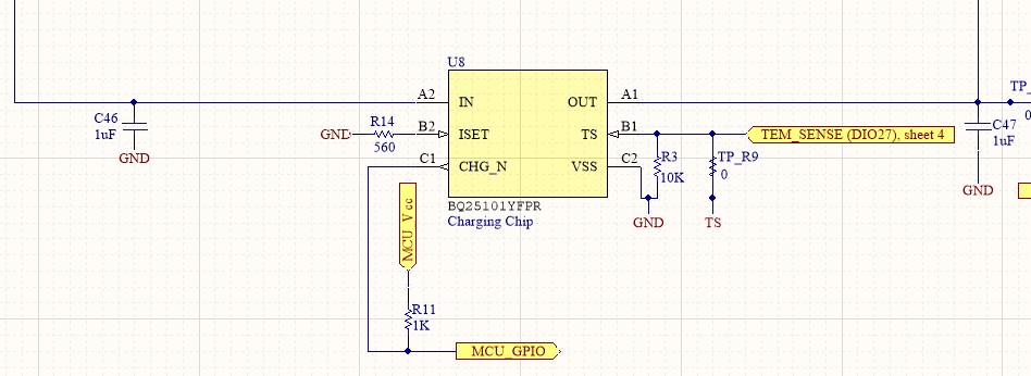
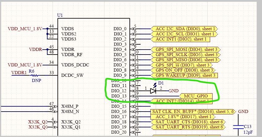
I know that the CHG' pin can be used as host monitoring and visual indication when charging. I would like to use CHG' pin for both host monitoring and visual indication at the same time.

Please help to verify the schematic on 'CHG_N' pin. Am I making the right connection?

Thanks

  • Hello

    The input is voltage from USB could overshoot, BQ251010 has input overvoltage protection up to 30V.  The CHG pin is max voltage is 7V.

    What is the max voltage on your MCU GPIO?

  • Hello

    A safe approach would be to use a small external MOSFET to drive the LED.  Gate of the MOSFET and MCU GPIO would be connected to BQ25101 CHG.  Pull up for the CHG pin would come from MCU VCC.  This would isolate the MCU circuit from possible input voltage transients.  LED would be powered from the input voltage.

  • Hi,

    Max voltage for MCU GPIO is 2.1V.

    MCU VCC is 1.8V.

    Thanks

  • Hi,

    I have made the changes based on the feedback. How about now?

    Thanks

  • Hello

    You have Q2 shown as a N-Type MOSFET but connected as a P-Type was this planned?

    Would need to use a P-Type connected between ground and cathode of D1.  May need a Source to Gate pull up resistor to keep it off.  I am working on a sketch.

    Another possible configuration if the MCU has another GPIO is to drive the Gate from MCU.  N-Type MOSFET between ground and cathode D1.  Drive low to turn OFF and to +2.1V to turn ON. 

  • Hi,

    Because P-Type would need a negative voltage to turn ON.

    N-Type enhancement MOSFET has switching characteristic of :

    Vgs = 0 , Off, Open switch

    Vgs = +ve , On, from MCU Voltage +1.8V

    I would like to let the MCU knows the charging state and at the same time turning on LED.

    Please share the sketch for clearer MOSFET connection.

    Thanks, Bill.

  • Hello

    I have attached a possible circuit that will used the MOSFET to isolate the MCU signal / voltage from USB 5V line.  

    BUT -- I should have pointed out that max voltage rating of  /CHG pin is 7V.  USB input has the risk of voltage spikes from a number of causes.  The voltage INPUT is rated for 30V max.  The below circuit has no additional voltage protection for the /CHG pin.

    Many designs will power the /CHG LED from Battery or other lower voltage source.

    LED + MCU interface.pdf

  • Hi,

    Thanks for the schematics and suggestions.

    Based on the schematics, I understand that:

    During charging, CHG_N open drain internal FET is ON (closed switch), current will flow through CHG_N pin. Therefore, external FET is OFF (open switch) which result in MCU-GPIO being pulled HIGH (indicate charge) through 10k pull-up to MCU-VCC.

    During charging complete, CHG_N open drain internal FET is OFF (open switch), current will flow through external FET Gate. Therefore, external FET is ON (closed switch) which result in MCU-GPIO being pulled LOW (indicate charge complete) to ground.

    I think during both charge and charge complete, the LED will always turn on.

    Should the LED placement be closer to the CHG_N pin, so that the LED is only ON during charging and OFF during charge complete?

    Correct me if I am wrong.

    Thanks, Bill

  • Hello

    Recommend using a small signal N-Type MOSFET for the external MOSFET, similar to BSS138. 

    "During charging complete, CHG_N open drain internal FET is OFF (open switch), current will flow through external FET Gate. Therefore, external FET is ON (closed switch) which result in MCU-GPIO being pulled LOW (indicate charge complete) to ground."  --Bill J - The gate of external mosfet will behave as a capacitor (no current flow).  During CHG_N open (Hi-Z) no current flow in the LED, external mosfet off.

  • Hi,

    Does that mean the external MOSFET will always OFF?

    If that's the case, when is MCU-GPIO LOW to inform MCU charging is complete?

    Thanks

  • Hi

    A low on the CHG pin turn the MOSFET off.  When CHG is floating the node is pulled high thru resistor and LED turning MOSFET on.

    You may want to consider powering the LED / CHG from Battery (OUT) this would avoid any overvoltage issues due to input voltage.

  • Hi Bill,

    I made some changes on CHG_N pin configuration.

    1. CHG_N pin will let MCU GPIO knows the charging status of the chip.

    2. Then, a seperate MCU GPIO connected to an LED will be programmed to turn on or off the LED accordingly.

    MCU used is CC2642R.

    Thanks, Bill

    Please check the 2 schematics below:

  • Hi

    This looks good.