This thread has been locked.

If you have a related question, please click the "Ask a related question" button in the top right corner. The newly created question will be automatically linked to this question.

LCD Backlight Requirement

Other Parts Discussed in Thread: TPS61185, TPS61165, TPS61080

Hi,

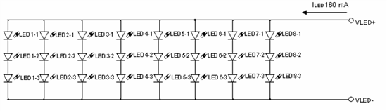
I am looking for a suitable cost effective backlight driver solution for 7" LCD display which has 8 strings of 3 LED, with all the strings connected in parallel requiring a current of 160mA total @ 9.9V as given below

The circuit has only 3.3V input. Suggest a suitable solution.

Regards,

Sridevi 

  • For the best matching of the current between the strings, you could use the TPS61185, with the boost stage powered by the 3.3V rail and the IC itself powered from 4.5V or higher as explained http://focus.ti.com/lit/an/slva434/slva434.pdf.  Another option would be to add small (5-10ohm) ballast resistors between the strings to improve the current matching or perhaps current mirrors as explained http://focus.ti.com/lit/an/slva270/slva270.pdf and simply use the TPS61165 to drive the LEDs.

  • Thanks for the info. Hope this is applicable for the case having multiple strings separately.

    But in my case as you see the LED arrangement, the strings are not separate. We just have single VLED+, VLED- with respect to the LCD connections. 9.9V @ 160mA is required across this connection.

    1. I think TPS61080/1 will be ideal for this. Pls advice.

    2. I would like to know whether the backlight dimming via PWM signal is possible with this device TPS61080/1 either via EN or SS. Pls advice. Would like to know the detailed functionality of SS of this device.

    3. As per the fig. 24 given below (refer datasheet of TPS61080/1), how is dimming functionality via PWM implemented? Pls detail.

  • The TPS61080 would not be my first choice for this application.  I would recommend the TPS61165 first.

    Regarding your answers to 2 and 3, PWM dimming  is performed by driving the SS pin voltage.  The SS pin voltage is the reference voltage for the IC until that voltage is clamped at the 1.2xV reference voltage.  The SS pin voltage is created by a constant current source that typically drives a capacitor.  In a voltage regulatin configuration, the output voltage follows the capacitor voltage rise.   But by placing a resistor on the SS pin instead of a capacitor, the SS pin voltage is clamped to Iss * Rss.  This in term sets the voltage to which the converter regulates at IFB.  This, in an LED configuration,  ILED=Iss*Rss/Rset.  You can dim by using the FET shown in the figure above to either short out resistor R1 or change a different current value with a second resistor R2.