This thread has been locked.

If you have a related question, please click the "Ask a related question" button in the top right corner. The newly created question will be automatically linked to this question.

new test with TPS40055

Other Parts Discussed in Thread: TPS40054, TPS40055

Peter

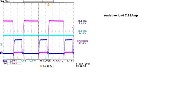
I made the modifications,using a bench with a variable resistor as Load i can get the system working till 6 Amp at 14Vout this means 7*14=84 Watt.

I put in and take out the load the system is working correctly.

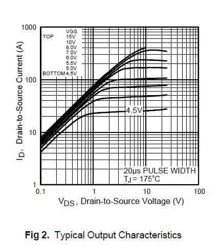
But, my load is a full bridge as You can see in the schematics that is driving two pulse transformers. each pulse transformer is a 1:1:1:1:1 so one primary 4 secondary, each secondary drives in X 3 fet each each fet is a rafly 20nF gate capacitance. the main inverters switches from 1kHz in PWM ZCS when loaded at lighest power continuous mode to 20kHz always in PWM ZCS high power continuous mode, anyway in continuous mode the load is very light also because for the 12 Vdc power supply the frequency of working is low.

When the system is working in discontinuos mode the highest frequency can be 220kHz and the run can be at least 6 seconds and after stop So the worst case for the 14 Volt PWs is when it runs at 220kHZ; so for each fet of the inverter we need a power given by the equation

CV^2 * Fsw so P= 20*10^-9*(28^2)*220*10^3= rafly 3.5W

so 24 fet to be driven P=24*3.5=84W

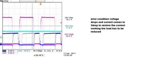
That is the power I get out with the resistive load. Now, when i load the 14 Vdc PWs with the ''BRIDGE LoAD'' the PWS in 100us start with the one pulse long one short the out voltage drops at 10 volt and till the load is applied the system works in this way.

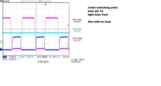
Bu looking at the switching point what i do not understand is, by changing from no load condition to load coundition the waveform at the switching point is nnot enlarging the

working duty cycle but is changing a litte bit the shape it becomes from a pseudo trapezoidal to a quasi rectangular

as showed in the pictures


What can I do? where i'm wrong regards mganzetti

  • Massimo,


    You're not getting something wrong so much as running on the edge of the TPS40054's capabilities in your circuit design.  First, I would try increasing the current limit a little bit higher as you still appear to be running into maximum duty cycle.

    Second, I would review the minimum source voltage that you need to operate this supply at.  You said this is a 24V regulated input, I would recommend using 20-22V as Vin(min) in the Rkff equation in the datasheet to ensure you have the maximum available duty cycle at 24V operation.

    Finally, you could consider increasing the capacitor from VIN to ILIM from 100pF to 470pF or even 1000pF.  The purpose of this capacitor is to help ILIM to track ripple on the input voltage.  The ILIM pin has a parasitic capacitance of about 10pF, at 100pF across Rilim, the ILIM pin moves about 90% of any ripple on the input voltage, however this means roughly 10% of that ripple impacts the current limit.  If you increase this to 1000pF the ILIM pin moves about 99% of the ripple on the input voltage, reducing the ripple's impact on current limit to only 1%.

  • thanks Peter,


    Now i'll do the change of the capacitor

    For the Rt resistor I choose 150k+10k+10k to get rafly 300kHz

    so by the equation Rkff=(20-3.5)*(58.14*170+1340) kOhm=185kOhm now on the board i have 150k+47k+47k=244k is it too high?

    Rhys=Rkff x (Vpd-3.5)(0.2*(Vinmin-3.5)=185*(8-3.5)/0.2*(20-3.5)=832.5/0.2*16.5=252k  now i have 244k


  • Massimo,


    No, I don't think 244k is too high, though Rhys might be too low.


    The KFF pin is current driven.  With Rt = 170kOhms it takes approximately 80uA of current into the KFF pin to trigger UVLO and once on the current has to drop to about 72uA to shut off and your Rhys is driving about 18uA of extra current into the KFF pin, adding about 4.4V of hysteresis.  If you don't need this much additional hysteresis, you could consider removing or increasing Rhys.

  • Peter,

    No way to make it overcrossing 5.9Amp

    well I increase the cap of Ilim to 470pF no improvement

    so i take out the Rhys but all just as before

    What I do not understand is why in no load condition the upper fet is conducting so long,

    I usually use PWM fixed frequency or variable frequency ZCS or ZVS and the load is setting my regulator to

    the correct duty cycle or working frequency, Why here not.

    Is that any chance to disable the safeties in this controller.

    I think that my power stage is enuogh powerfull 110Amp pk fet at 55Volt may i improve current by reducing voltage

    i mean 30V fet with 150Amps


    regards

  • Massimo,


    The TPS40055 controller is a fully synchronous, fixed frequency BUCK converter, even at zero load, the synchronous rectifier is driven fully complementary to the main switching FET so it's duty cycle is nearly the same at no load and full load.  Fro 24V to 14V, this is about 60%.

    You can disable current limit by removing the resistor between VIN and ILIM.

    I did some graphical comparisons between your No-load operation and 7A operation above.

    1) At 7A load current the switch node pulse width is approximately 150ns longer than at no-load.  This is the TPS40055 controller's error amplifier loop compensating for the losses in the Power Supply.  This would represent 6.5-7W of loss being compensated.

    2) The SW voltage at the of the switching cycle is 1V - 1.2V lower at 7A load current than at No-load.  If the Input voltage is actually 24V, the voltage drop to the switching node appears to be 1.5 - 1.7V.  The switch node dropping so low would be consistant with the supply still entering current limit.


    You may want to check the DC voltage at the drain of the high-side FET at No-Load, 3A and 6A plus the AC ripple on the drain voltage at the same 3 load current.  These numbers are suggesting that you're experiencing a lot more drop from your 24V source to your power supply than expected.

  • Hi Peter,


    well,  Yesterday I disable the UVLO and feed forward using the equation on SLUA310

    I put a 13k resistor in between pin 1 and 3, and no RkFF but the problem was still the same.

    By reading Your last post i first look at the 24Vdc, the supply drops of about 0.7 volt when 6Amp.

    So I disable the current check, the system is now giving 14Vdc with 10 Amp without any problem

    I made measurement on the voltage drop and in no load I get 24Vdc

    with 6 Amp rafly 23.2

    at 10 Amp the drop is about 1 volt

    now i was checking with a differential probe the voltage on the upper mosfet in between drain and source,

    I think that's good,in  comparison with SW node I get only some ringing at turn off and on

    So the two questions are:

    is there any problem to use the device with the Ilim disable? (i think no)

    I look at the mos I use now the IRF3205 well are no logic level mosfet so can be also that the 8 volt gate

    given by the device is not enough to full saturate the mos, do You think that could be usefull to try to use

    the IRL3803 that is a 30 Vdc device 140 Amp but is also LL device

    what I do with the Rkff should i try to restore the olds circuit?


  • is there any problem to use the device with the Ilim disable? (i think no)

    Aside from the lack of power-stage protection due to a shorted output or excessive load current, no.  The IC will perform all other functions independant of current limit.  For the purpose of IC pin protection, I would recommend populating the RILIM resistor position with a resistor between 330 - 510kOhms to disable the function.  This prevents the ILIM pin from floating and being subject to noise injection.

    I look at the mos I use now the IRF3205 well are no logic level mosfet so can be also that the 8 volt gate

    given by the device is not enough to full saturate the mos, do You think that could be usefull to try to use

    the IRL3803 that is a 30 Vdc device 140 Amp but is also LL device

    If we look at figure 2 from the IRF3205 datasheet

     We see that even with a junction temperature of 175C the MOSFET's 8V Vgs saturation current is over 200A with a forward current of 60A representing a 1V forward drop.  Even at these elevated temperates, the forward drop across the FET at 10A should be less than 200mV with a gate drive as low as 5V.  Using the TPS40055 controller, which provides 8-10V of gate drive voltage, the IRF3205 should be fully saturated.


    The IRL3803 does offer a lower Rdson at 8V verse the IRF3205, however it does it at significant expense in switching speed.  The IRL3803 MOSFET has 50% more switching charge (100nC verse 70nC from maximum datasheet specifications) and considerably higher total gate charge at 8V gate drive (140nC verse 78nC from typical Vgs verse Qg curves) It is unlikely that the improvement in Rdson will overcome the significant increase in driver current, switching and gate drive losses.

  • Peter,


    Thanks for Your Help


    regards

    Massimo