This thread has been locked.

If you have a related question, please click the "Ask a related question" button in the top right corner. The newly created question will be automatically linked to this question.

LM76202-Q1: IMON pin reference potential

Part Number: LM76202-Q1

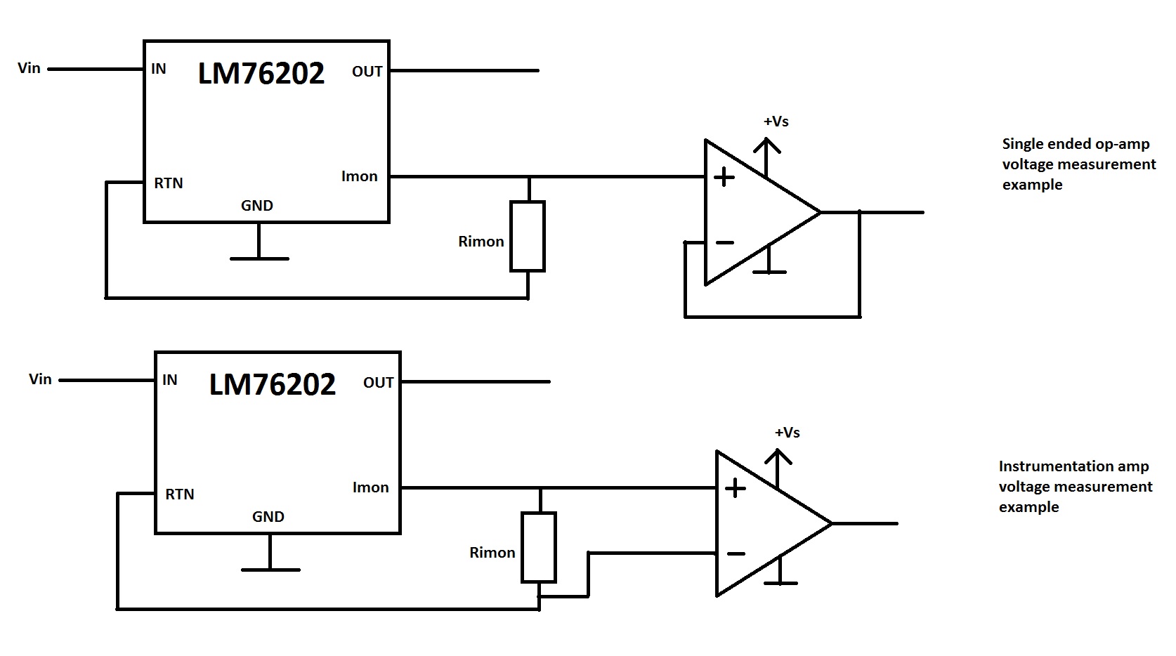
Hello, we are considering using your LM76202 ideal diode in an automotive application because it has current measuring capability. I was wondering is it safe to assume that IMON pin which serves to output monitoring voltage is referenced to GND of the IC? I connected an instrumentation amplifier across Rimon resistor to measure the voltage that is proportional to load current, but after some thought it seems in the reverse polarity condition input of that amplifier would see a reverse voltage and potentially get damaged. Below is the example of posible measurement setups.

To put it simply is it safe to make both differential (with instrumentation amplifier) and single ended voltage measurement across Rimon resistor or only single ended measurement (using e.g. op-amp with input connected directly to Imon pin)? We think that because of your reverse polarity protection circuit inside the chip in the case of differential voltage measurement input of the instrumentation amplifier would see large negative voltage potential in the case of reversed input polarity, and I would like to find out if that is true.

Thanks

  • Hi,

    Thanks for reaching out.

    We will get back to you early next week.

    Best regards,  Rakesh

  • Hello Luka

    Welcome to TI E2E forum and thanks for considering LM76202-Q1 for your application !

    Your understanding is correct about device operation during input reverse polarity. I would recommend adding series resistor and a schottky diode clamp to limit the current through op-amp sensing circuit in case of reverse polarity condition. With single ended configuration, you would need a series resistor from IMON to op-amp non inverting terminal (positioned after IMON sense resistor) to limit the current folowed by a schottky diode (anode to op-amp GND).

    A schottky diode will make sure op-amps internal ESD diodes do not conduct during negative voltage input and series resistor will limit the current through schottky.

    What would be the voltage level in case of reverse polarity? Do you have a snap shot of schematic that can be shared?

    Thanks & Regards

    Abhijeet

  • Well the schematic is pretty simple, it is similar to your reference design, but with tweaked values regarding current ranges, and we will use single ended measurement configuration with precision op-amp. We expect about 50V in case of reverse polarity condition.

    You are right about limiting the current, I will add that protection in series with non-inverting input because in the op-amp datasheet it is specified that it must not rise above 10mA through ESD protection.

    Thank you for your help,

    Luka