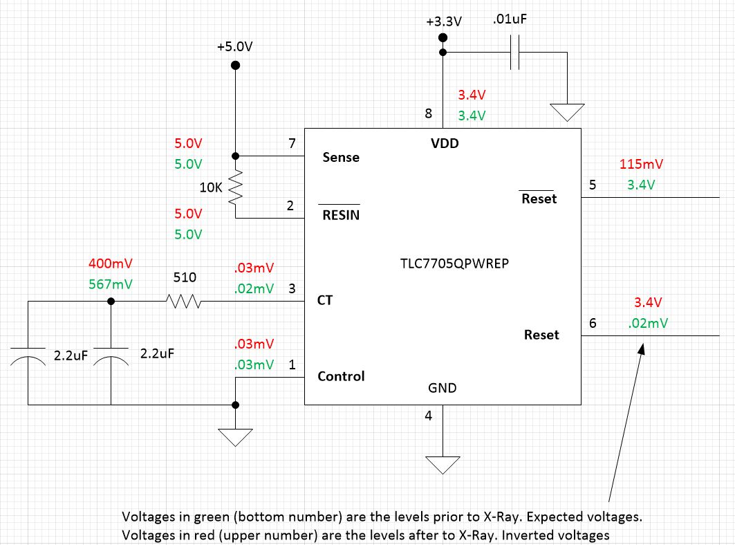
We use the TLC7705QPWREP as a power on reset. The circuit was working prior to exposing the board to x-ray examination. After the x-ray examination (<100rads exposure) the reset outputs were inverted. The schematic attached shows the voltage measurements pre and post exposure.
Is it possible that the x-ray examination damage/changed the part?
Could the 5V input voltages with a VDD=3.3V cause this inversion?
I was going to try and insert a Visio schematic but that did not work. Circuit is hooked up as follows:
Vdd = 3.3V; Sense goes directly to +5V; RESIN/ goes to +5V via 10K resistor; CT goes to 4.4uF via 510 ohm resistor; Control goes to GND (pin4); In this condition the Reset/ is normal 3.4V and the reset is .02mV. After subjecting the board to x-ray, reset/ is 115mV and reset is 3.4V.