This thread has been locked.

If you have a related question, please click the "Ask a related question" button in the top right corner. The newly created question will be automatically linked to this question.

TPS2490: Timer Capacitor(Ctimer) Value

Part Number: TPS2490

Dera, Sir.

I would like to confirm about the timer capacitor(Ctimer) value.

Please give your advice.

1. My custoer is putting 1uF as the timer capacitor(Ctimer).

   Accoring EVM, Design calculator, the value looks smaller than that.

   Is there the recommendation value range for the capacitor?

2. If the charging(sourcing) time was too long, so much heat woukd be produced.

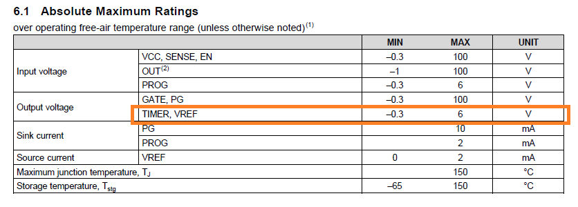
  The datasheet defines min. 15uA & max. 35uA.

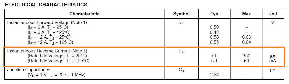
  I wonder the current would be decreased  or increased under higher temperature?

3. If you have another concern to put the large value capacitor, Please let me know.

Best Regards,

H. Sakai


  • Hi Sakai,

    The max Ctimer value that can be used is determined by the system operating parameters and FET SOA. If the design sheet meets SOA for 1uF, you can proceed with out any concern.

    Can you please detail your second question.

    BR, Rakesh

  • Dear, Rakesh-san. 

    The customer's system condition are ; 

    - Input voltage : 24.5V

    - RL : 0.3ohm

    - Current limit setting : 20A

    - Ctimer : 1uF (160ms) 

    1. Under above condition, they confirmed the timer period is 272ms versus calculated value 160ms. 

       They are asking the reason why there is a big difference. 

    2. As you mentioned, FET's SOA will be so important. Do you mean 1uF value capacitor & 160ms 

        timer period is not suitable considering existing FET's SOA? 

    Best Regards, 

    H. Sakai

  • Hi Sakai-san,

    Can you please share

    1. Schematic
    2. Filled up design calculator
    3. Test condition under which above issued observed
    4. Test waveforms.. Include
      1. Vin, Vout, GATE, timer voltage
      2. Vout, GATE, timer voltage, input current 

    BR, Rakesh

  • Dear, Rakesh-san. 

    Thank you so much for your support. 

    I requested the customer to provide the information as you pointed, but have not 

    obtained, yet. 

    I believe the timer function will be simple to act the charging & discharging with the 

    external capacitor. If it was true, no result why the timer period become so long after

    the schematic or setting checking. 

    At this time, I would like to confirm about the characteristics protection diode. 

    According the datasheet, the protection diode will be located GND to TIMER pin. 

    For instance, the discrete SBD has the reverse current(IR_leakage) and it has the thermal co efficiency.

    I am guessing it influenced the timer period to be longer, especially under higher temp.  

    Is it possible to confirm the IR of protection diode &  the thermal co efficiency? 

    You don't need to assure that, the design spec is enough. 

    It was depended on the results, but possible to make the final answer without your loading for the checking. 

    Best Regards, 

    H. Sakai

  • Hi Sakai-san,

    The timer sourcing current has variation from 15uA to 34uA with 25uA as typical. This variation accounts for all the process, temperature and internal circuit tolerances.

    For 1uF timer cap, the typical timer period is 160ms; max timer period is 266ms and min timer period is 117ms.

    Can you share few more details...

    1. Part number of 1uF timer cap
    2. Is the behavior of longer timer period observed on single device or multiple devices ?
    3. what is the timer period when low value of timer cap is used ? for example 100nF timer cap

    BR, Rakesh

  • Dear, Rakesh-san. 

    Thank you so much for your reply. 

    Shall we talk via our private mail. 

    Best Regards, 

    H. Sakai

  • OK. Will follow up on email.

    Regards, Rakesh