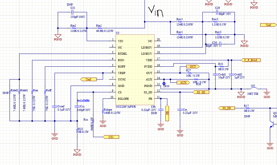
I am trying to use the UCC2897A chip for 120V input, using a resistor divider circuit at the VIN pin of the chip as shown in the schematic diagram. The values of Rin1 and Rin2 actually used are 25Kohm each. The voltage at the VDD pin is 11V using the series regulator circuit available in the application note "Understanding and Designing an Active Clamp Current Mode Controlled Converter Using the UCC2897A". Now the problem is if am giving 60V input voltage, then the voltage at VDD is 11.57V, and it is not going above 12.7V, which is needed to start the chip. And the voltage across the Rin2 pin is also 11.57V, so the voltage across the Rin2 is 48.43V. So the current through the Rin1 will be around 1.9mA. Where is this current going? Why it is not charging the VDD capacitor?