This thread has been locked.

If you have a related question, please click the "Ask a related question" button in the top right corner. The newly created question will be automatically linked to this question.

TPS92641: Comp capacitance

Part Number: TPS92641

Hi,

On figure 11 of following application note, the comp capacitance is 2.2nF.

http://www.ti.com/jp/lit/an/snva725/snva725.pdf

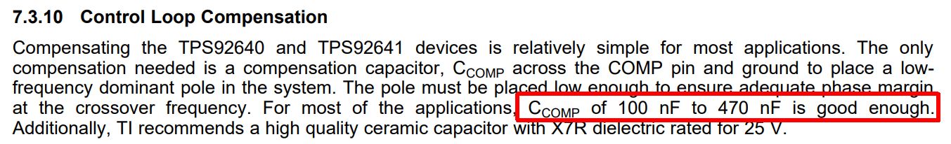
On the other hand, it is recommended 100nF~470nF on the datahseet.

Is 2.2nF correct?

Best Regards,

Kuramochi

  • Cvcc and Cboot are also out of recommended value on application schematic.

    Is this schematic verified?

    Best regards,

    Kuramochi

  • Hello Kuramochi,

    The design you are referring to was done be a different group for a different application.  The Comp capacitor value at 2.2 nF can be needed if the response time needs to be faster.  The recommendation for Cboot = 0.1 uF is just a recommendation.  If you look at the EVM it uses a 0.22 uF boot capacitor. Sometimes for long off-times the capacitor may need to be a larger value.  Note that it would be recommended to have a larger VCC capacitor with a larger Cboot capacitor.  Other Texas instruments LED driver ICs recommend 10X value of Cboot for CVcc.  This is because the VCC capacitor has to charge Cboot from as low as typical 1.6V.  Also the diode stress can also go up with a large Cboot capacitor.

    The values you are referring to are operation specific.  The Comp capacitor value recommendation of 100 nF to 470 nF is conservative allowing many operating ranges being stable.  These values depend on what the design and what operating conditions it needs to handle.

    Best Regards,