This thread has been locked.

If you have a related question, please click the "Ask a related question" button in the top right corner. The newly created question will be automatically linked to this question.

LP5569: Dual LP5569 using with Other MCU Models...

Part Number: LP5569

Hi for One.

 Brief Description of my purpose is that;

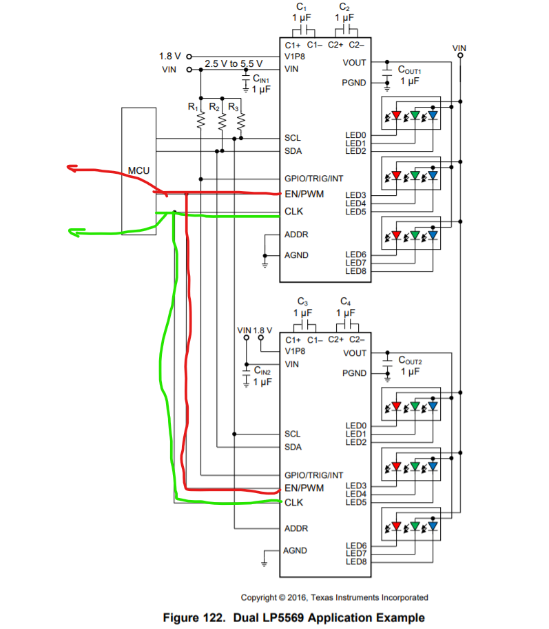
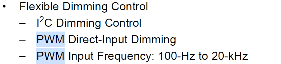
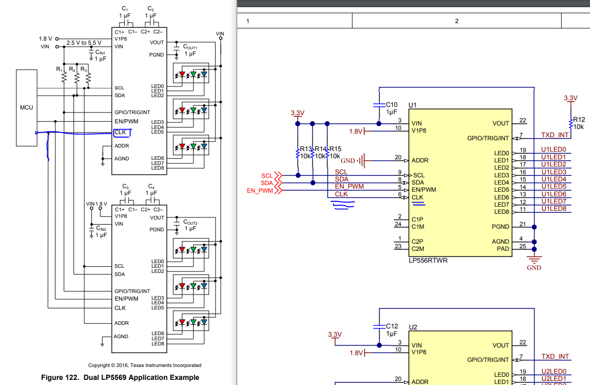
 As you can frequently see your surrounding, colorful ethernet device in home and at  offices(https://www.google.com/searchq=google+wifi+mesh+colorful&tbm=isch&ved=2ahUKEwi02JXV_cvnAhUS8hoKHWyAAWQQ2cCegQIABAA&oq=google+wifi+mesh+colorful&gs_l=img.3...56914.64384..64732...3.0..0.221.2315.0j14j1......0....1..gws-wiz-img.14P-wqgyNy4&ei=IutDXrS_N5Lka-yAhqAG&bih=881&biw=1745&rlz=1C1CHBF_enCY852CY852#imgrc=Pglflwuj_RKWLM). for that applications, we would like to provide colorful view using RGB Led which is being controlled by LP5569. for that aim, couple of LP5569 will be used  but as MCU, MT7620A(https://www.datasheetq.com/datasheet-download/190926/1/MediaTek/MT7620) will be used but for that embedded system design. l have some trouble for pin configurations.and have found meaning overlap for connections. 

-For example as l shown in figure marked blue CLK pin what should l do for that CLK pin?

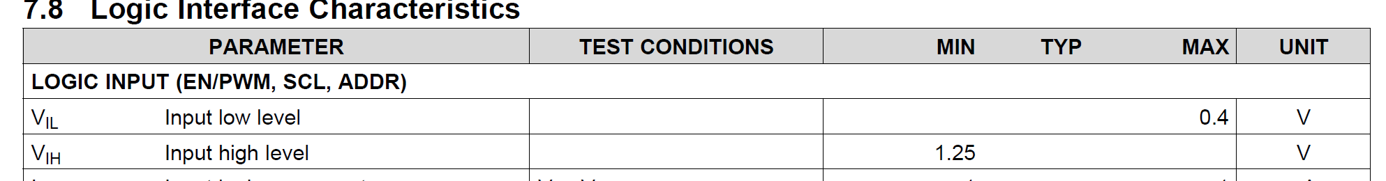
For CLK pin, can l use any GPIO(at page 1 from http://www.ti.com/lit/df/tidrwk9/tidrwk9.pdf), any Oscillator Pin or connection with 3.3v is enough?

-For GPIO /TRIG/INT, in dual usage  require any GPIO Connection from MCU , what should l do for that?

- Question on VOUT pin configuration,

for Dual usage of LP5569, We have to deal with VOUT using or not? because in reference design, not connected to any RGB LEDs  but in Dual Application 

  • Hi Mustafa,

    Proper engineer has been assigned to look at this and will reply to you soon.

  • Hi Mustafa,

    1) CLK pin is for external clock input. You could use GPIO or oscillator to generate a 32kHz clock for it. Detail requirement of clock could be find at datasheet page 8.
    If you do not use engine function, you could directly connect CLK pin to GND or VIN. This clock is for synchronization of 2 LP5569 engine running.

    2) GPIO/TRIG/INT pin defaults as INT. It is also for engine function and could be left floating if not used.

    3) If charge pump is used in your design, a 1-uF capacitor must be connected between PGND and this pin. If charge pump is not used or is used in 1x mode only, the capacitor can be omitted.

  • in my design ,if l use the  sample way from DataSheet as Shown in figure attached, where  should be Red and Green Lines connected from MCU?

  • Hi Mustafa,

    It depends on if you need to use below functions.

    1) EN/PWM is used for global PWM input. If you do not want to use it, you can connect it to VIN or a GPIO set at high level. 
    2) CLK is used for external CLK. If not used, this pin must be connected to GND or VIN. If you need to use it, you can connect it to a GPIO which can generate 32.7kHz signal. Details can be found at section 7.11 of datasheet

  • Questıon 1.

    in my CPU Model( MT7620A), there is no PWM Pin, for that reason,What shall l do ?

    lf l connect the EN/PWM to VIN, it will be active always whenever VIN is ON? 

    Question 2.

    For CLK pin, if l connect CLK pin to


    Shortly,what l want to design is to do as  shown in attached photo(Fıgure122). as l understood from your feedback, l will connect the EN/PWM to GPIO  and also for CLK pin, l will connect the CLK pin to any GPIO on my CPU, Right ? Agree with me?

  • Hi Mustafa,

    1) You could connect EN/PWM pin to a GPIO pin of your platform, where can generate below PWM signal. If you connect it to VIN, you also need to write chip_EN register to active the device.

    2) If external CLK is used, it is recommended to be connected to GND or VIN. You could connect it to a GPIO but cannot left it float.